Research Article - (2024)Volume 13, Issue 1
Building Information Model for Cost Estimation and Scheduling in Building Architecture
Mohammad Zia Rahimi1* and Hasibullah Khan2Abstract
Building Information Modeling (BIM) is a prominent and severely needed development in the Architecture, Engineering, and Construction (AEC) industries. BIM is both a technology and a process, BIM technology allows for the digital construction of an accurate virtual model of a building. Green building development is supported by Building Information Modeling (BIM), a contemporary data information platform and management tool. In this research, two building performance analysis software, Autodesk Takeoff and Navisworks including Revit to make the BIM model have been used. First presented in this paper are the main concepts of BIM then a BIM model integration for cost estimation, and construction schedule are considered using the above BIM analyzing tools. This study presents thorough cost estimation and scheduling methods using the BIM model. The model and BIM are coupled to allow the user to calculate estimation and construction schedule analysis facilities.
The research methodology involved qualitative and quantitative data collection, cost, and schedule analysis. The results reveal significant Improvements in the BIM model and its integration with other software and demonstrate the potential of BIM in promoting a concise and digital model.
Keywords
Autodesk; Building Information Modeling (BIM); Cost; Estimation; Model; Schedule
Introduction
The act of creating an electronic model of a facility for visualization, engineering analysis, conflict analysis, code criteria checking, cost engineering, as-built product, budgeting, and many other purposes" is the definition of Building Information Modeling (BIM). Establishing a common vocabulary to explain the targeted application of BIM on a residential project is crucial for improving industry communication. "A method of applying Building Information Modeling during a facility's lifecycle to achieve one or more specific objectives" is one way to define a BIM use [1].
However, the term "BIM" and its concept are not new; they weren't in 1997, 2002, or even 2007. The anticipated cost of building the model is 0.1% of the total cost of construction. The term "Building Information Model" has been in use for at least fifteen years, but the ideas, strategies, and techniques that we now refer to as BIM stretch back nearly thirty years. This technique Afghanistanor approach was most frequently stated in the early 1980s in the USA as “Building Product Models” and in Europe—especially in Finland—as “Product Information Models” [2].
BIM Model is integrated with different software. A BIM model is sustainable, energy-efficient, environmentally protected, and a comprehensive representation of a building from the point of construction until the end phases. In this research a BIM model is made using the BIM tool Revit Architecture, then it is analyzed using the cost estimation of the project, and the model is uploaded to Autodesk Take off. For construction scheduling analysis the model is then imported to Navisworks. The general background of the study is to analyze the BIM model, since it’s integrated the same model can be used to automatically analyze energy efficiency, cost estimation, and construction schedule. Each of the processes is detailed and described further in this research although computer-aided design research from decades ago served as the foundation for BIM, there is currently no universally recognized meaning for the term. BIM is referred to as "an intelligent simulation of architecture" at the M.A. Mortenson Company. For us to accomplish integrated delivery, this simulation needs to have six essential features. It has to be. M.A. Mortenson Company.
• Digital,
• Spatial (3D),
• Measurable (capable of being quantified, dimensionalized, and queried),
• All-encompassing capturing and conveying the design intent, constructing
• Constructability, performance, and encompass financial and sequential elements of means and procedures
• Accessible (to the entire AEC/ owner team through an interoperable and intuitive interface)
• Durable (usable through all phases of a facility’s life).
What are not BIM technologies?
• Models with only 3D data and no object properties.
• Models with no support of behavior.
• Models that require the fusion of several 2D CAD reference files to describe the structure.
• Models that permit dimension modifications in one view but do not instantly update other views [3].
Benefits of BIM
The owner's benefits before construction:
• Concept, viability, and advantages of design
• Enhanced performance and quality of buildings [4].
Design advantages:
• Earlier and precise designs visualizations
• Automatic low-level adjustments upon design modifications
• Produce precise and uniform 2D drawings throughout the design process
• Boost sustainability and energy efficiency [4].
• Advantages for fabrication and construction
• Coordinate planning for design and construction
• Find mistakes and omissions in the design before construction [4].
Post construction advantages:
• Improve facility management and operation
• Connect to management and operation systems for the facility
Owners can use a building information model
• Boost total building performance and building value with BIM-based energy design and analysis
• Reduce the time it takes to approve and complete a project by utilizing building models to coordinate and prefabricate the design with less field work.
• Using automatic quantity take-off from the building model, obtain trustworthy and precise cost estimates. Offer input early in a project, when decisions will have the biggest influence.
• Verify program compliance by continuously comparing the building model's specifications to those of the owner and local codes.
• Create facilities that are ready for the market by shortening the period between procurement choices and real construction, enabling the use of the newest trends in finishes or technologies.
Symmetric items
Grasp BIM and how it differs from conventional 2D objects requires a grasp of parametric items. The definition of parametric BIM objects is as follows [5]:
Different levels of aggregation, associated data, and rules, non-redundantly, automatically modifying associated geometries, and object feasibility.
Instead of creating an instance of a building element, such as a wall or door, a designer using parametric design defines a model family, also known as an element class, which is a collection of relations and rules that control the parameters by which element instances can be created, each of which will differ depending on its context. A parametric modeler's shape and assembly geometry automatically adapt to contextual changes and high-level user controls, whereas traditional 3D CAD requires users to manually alter every facet of an element's geometry. Building Information Modeling (BIM) tools are conceptually object-based parametric models with a present set of object families, each of which has the behaviors previously mentioned built into it. Certain parametric relations to complicated curves and surfaces, such as splines and Non-Uniform B-Splines (NURBS), are supported by certain BIM design tools. These tools enable the definition and manipulation of intricate curved shapes in a manner akin to other forms of geometry. These features are absent from several popular BIM programs on the market, maybe due to dependability or performance issues. Geometry can be created and edited with great power using parametric object modeling [4]. The mechanical engineering community discovered with considerable regret that, in the absence of it, model generation and design would be incredibly laborious and prone to error [3]. Without a framework that enables efficient low-level automatic design modification, designing a building with a million or more objects would be impossible. In 2002, Autodesk released Revit Architecture TM, their first BIM solution, to the market [4]. For architectural design and was swiftly embraced by the majority of BIM-using architecture firms. Following years of development, the Revit package is now a software that supports several uses for architectural design (Revit Architecture TM), plumbing and electrical engineering (Revit MEPTM), and structural design (Revit Structure TM) during the building process.
Compatibility
Organizations with varying roles and responsibilities are involved in the building lifecycle, and no BIM solution can serve every function required at every step of the building lifecycle. For the stakeholders, data sharing between applications is crucial since, in addition to the building's architectural design, there are other connected tasks including energy analysis, fabrication, cost estimation, scheduling, and structural and Mechanical, Electrical, and Plumbing (MEP) design. Data interchange at the software level is crucial since every action needs a different software program to support it. The following four methods define how model data can be transferred between two software tools [2]:
• Straightforward connections between particular BIM tools
• Exclusive exchange file format
• Formats for public level exchanges
• Exchange formats based on XML
BIM applications can export in the desired file format using these open standards, allowing another software tool to import and read it. The most often utilized exchange that an estimator plans to use is summarized, common exchange formats in AEC applications as shown in Tables 1 and 2. Autodesk Quantity Take off™ to create the amount take off list using a Revit Architecture building model. The design's default format, RVT, is not one of the file formats that Autodesk Quantity supports. Take off (DWF or DWG). However, Revit Architecture™ allows users to export the drawing with different file formats, such as DWG, DXF, or DWF.
| Image (Raster) formats | Descriptions |
|---|---|
| JPG, GIF, TIF, BMP, PIC, PNG, RAW, TGA, RLE | Raster formats differ in how compact they are, how many colors may be in a pixel, and whether they compress data or not. |
| 2D Vector formats | Descriptions |
| DXF, DWG, AI, CGM, EMF, IGS, WMF, DGN | Vector formats vary regarding compactness, line widths, pattern control, color, layering, and types of curves supported |
| 3D Surface and Shape formats | Descriptions |
| 3DS, WRL, STL, IGS, SAT, DXF, DWG, OBJ, DGN, PDF(3D), XGL, EWF, U3D, IPT, PTS | The representation of surfaces and/or solids, any material qualities of the shape (color, image bitmap, texture map), and viewpoint information all influence the different formats of 3D surfaces and shapes. |
| 3D Object Exchange formats | Descriptions |
| STP, EXP, CIS/2 | Geometry is represented in product data model formats based on 2D or 3D representations. They also carry relationships between objects and object characteristics. |
| Game formats | Descriptions |
| RWQ, X, GOF, FACT | The varieties of surfaces, including those with hierarchical structures, different kinds of material attributes, texture and bump map settings, animation, and skinning, all influence the different game file formats. |
| GIS formats | Descriptions |
| SHP, SHX, DBF, DEM, NED | Geographical information system formats |
| XML formats | Descriptions |
| AexXML, Obix, AEX, bcXML, AGCxml, IFCxml | XML schemas created for building data interchange. They differ based on the workflows that are supported and the information that is shared. |
Note: Common exchange formats in AEC applications (Eastman C. T., 2008).
Table 1: File formats and descriptions compatible with software.
| Product name | Manufacturer | BIM use | Supplier web link |
|---|---|---|---|
| QTO | Autodesk | Quantity Takeoffs | www.autodesk.com |
| Exactal | Exactal | Quantity Takeoffs | www.exactal.com |
| Innovaya | Innovaya | Quantity Takeoffs | www.innovaya.com |
| Takeoff Manager | Vico | Quantity Takeoffs | www.vicosoftware.com |
| On center | On center | Quantity Takeoffs | www.oncenter.com |
Note: The software list being used for takeoff (Author).
Table 2: List of Software used for quantity take off.
To produce an accurate take off list, the estimator can export the drawing in the desired file format and then upload it into Autodesk Quantity Take off. Further information about file formats that are supported by various BIM programs will be covered in the section that follows [2]. Because BIM is interoperable, users can transfer a more accurate and comprehensive building model with fewer errors and omissions from one organization's computer programs to another. As a result, at any step of the construction lifespan, all participating businesses can exchange consistent building model data.
BIM tools
An increasing number of software companies are integrating their products into the potential BIM space as BIM develops into one of the most cutting-edge technologies in the building sector [7].
Revit
The most well-known and dominant product on the market right now for using BIM in architectural design is Revit Architecture Autodesk introduced it. Following the program's acquisition by the business from its inception. With a distinct code base and file structure from AutoCAD, Revit is an entirely new platform. This review is for version 9.1. Currently available items in the Revit family of integrated solutions are Revit Architecture, Revit Structure, and Revit MEP. Direct connections to ROBOT and RISA structural analyses, gbXML interfaces for energy simulation and load analysis, and the capacity to import models from Sketchup, a conceptual design tool, and other programs that produce DXF files are some of its features. Among the viewing interfaces are: DGN, DWG, DWF™, DXF™, IFC, SAT, SKP, AVI, ODBC, gbXML, BMP, JPG, TGA, and TIF. Revit relies on 2D sections as a way of detailing most types of assemblies.
Revit’s strengths
Its functionality is arranged in an intuitive, well-designed interface, making it simple to learn. It features a large collection of object libraries created by outside parties. Due to its market position, it is the favored interface for direct link interfaces. Its strong object library supports a multi-user interface, it supports parallel operation on the same project, and its bi-directional drawing support enables information production and management based on updates from drawing and model views.
Revit’s weaknesses
When a project exceeds 220 gigabytes, Revit, an in-memory technology, performs noticeably worse. It is not compatible with parametric rules involving angles. It is also limited in its capacity to facilitate design with or reference to complex curved surfaces because it does not support them [8].
Strengths and limitations of object-based parametric modeling
The intelligent design behavior of objects is one of the main advantages of parametric modeling. Object-based parametric modeling, or BIM, is an improved form of parametric modeling technology [5]. That intelligence does, however, have a price. Every kind of system item has unique linkages and behaviors. BIM design tools are therefore by nature complicated. Every kind of building system is made up of variously generated and edited elements. Gaining skills with a BIM design tool typically takes months. Some designers' preferred modeling programs, like Sketchup, Rhino, and form Z, are not based on parametric modeling. Instead, they offer a set method for geometrically altering things that aren't affected by the surface types that are employed; this feature applies to all kinds of objects. A significant advancement in the building sector, object-based parametric modeling is making it easier to transition from handcrafted, drawing-based technologies to digitally readable models that can be shared with other apps. Although object-based parametric modeling had a significant role in the development and adoption of Building Information Modeling (BIM), it is not the same as BIM tools or the creation of building models.
Quantity take off and cost estimating
Cost data is the fifth dimension that the 5D model adds to the 3D model. To provide more precise project cost estimation, a 5D model connects the cost data with the Quantity Take off (QTO) list, which is produced from the 3D model [5]. To support the estimating process and use BIM for quantity takeoff, estimators have access to a range of solutions. Since no BIM tool can replace a spreadsheet or estimating software in its entirety, estimators must choose the approach that best suits their particular estimating procedure. The three alternatives for primaries are:
• Transfer the quantities of building objects to the estimate program
• Immediately connect the estimating program to the BIM tool
• Employ a quantity take off tool for BIM.
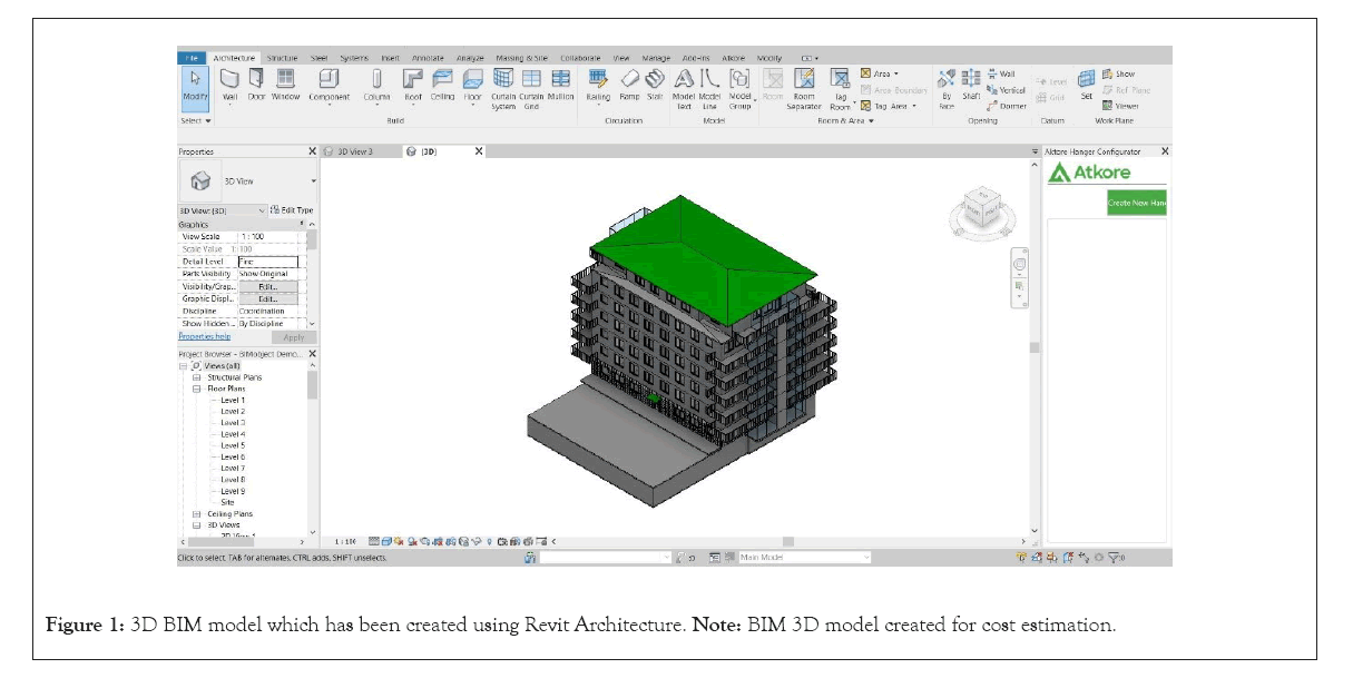
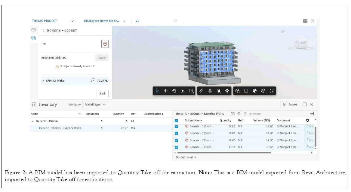
The third option is to employ a customized quantity takeoff tool that imports data from several BIM systems; this is depicted generically in as shown in Figures 1 and 2. As a result, estimators can utilize a takeoff tool that is tailored to their requirements rather than needing to become familiar with every aspect of a particular BIM product. Exactal, Innovaya, and Oncenter are a few instances of them. These tools usually include unique features that make direct links to assemblies and objects, annotate the model with "conditions," and provide takeoff diagrams that may be seen visually. The support for automatic extraction and manual takeoff features varies among these technologies. With a variety of takeoff and condition checks to complete, estimators will require a blend of manual instruments and automated functionalities. Autodesk QTO™ enables manual takeoff customization based on user preference and can automatically extract QTO from the building model as shown in Figure 2.
Figure 1: 3D BIM model which has been created using Revit Architecture.Note: BIM 3D model created for cost estimation.
Figure 2: A BIM model has been imported to Quantity Take off for estimation. Note: This is a BIM model exported from Revit Architecture, imported to Quantity Take off for estimations.
On category information provided on the object model. Following that, users can correlate the quantities with any appropriate cost database by exporting the QTO list to an MS Excel file. The QTO process in this approach can be finished by automatically classifying the items according to the "Category" data supplied to the object model. Users have the option to manually modify certain items on the QTO list following the automated takeoff. This method has the benefit of allowing users to map any appropriate cost data with the QTO list after the quantities are generated, thus they may not need to apply to the assemblies based on the particular cost estimating program. But as opposed to directly connecting parts to estimating software, this method may take more time to map the cost database Additional changes to the building model require that any new objects be linked to proper estimating tasks so that accurate cost estimates can be obtained from the building model, depending on the accuracy and level of detail already modeled [8].
4D Processes for Modeling Schedulers have a similar range of tools and procedures to pick from when creating 4D models as estimators do:
• Manual technique with 2D or 3D instruments
• 4D elements that are integrated into a 3D or BIM tool
• Import schedule and export 3D/BIM to 4D tool
Manual link, updates need to be made using a scheduled 4D tool or BIM-based procedure digital links, which automatically update as shown in Figure 3.
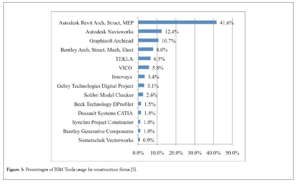
Figure 3: Percentages of BIM Tools usage by construction firms [5].
Autodesk navisworks™
The fourth dimension, or timetable, is added to the 3D model in the 4D model. Users can virtually simulate the project in a 4D environment by using a 4D BIM model, which connects the 3D elements with the project delivery timeline [5]. For the schedule and cost controls, Autodesk has Navisworks™ this enables the management and simulation of the building process, as well as Autodesk Quantity Take off Software, which facilitates cost estimation [9,10]. Apart from these, Autodesk™ also developed software tools such as Autodesk 3ds Max for model visualization and Autodesk™ Inventor for data exchange to benefit the users from higher control levels. Most of the software tools from Autodesk™ can support multiple file formats which include:
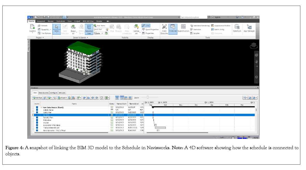
DGN, DWG, DWF, DXF, IFC, SAT, SKP, AVI, ODBC, gbXML, BMP, JPG, TGA, and TIF. The multiple file formats supporting function allows this software to be compatible with products from other software developers. Autodesk™ also provides free trial versions of the software and training webinars [11,12]. The ability to define the schedule itself may be included in some BIM scheduling software packages. Autodesk Navisworks™, which means the imported schedule will be linked to the objects of the building model. To calculate the schedule, Vico Control™ links the quantities of the building objects to a “recipe” that contains the description of materials, labor, resources, cost, and even location information. This integration of the 3D model and project schedule is called the 4D model as shown in Figure 4 [13].
Figure 4: A snapshot of linking the BIM 3D model to the Schedule in Navisworks. Note: A 4D software showing how the schedule is connected to objects.
Materials and Methods
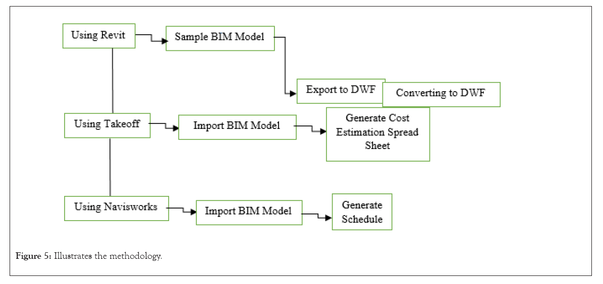
The methodology of this research contains multiple steps, sample BIM model creation using BIM tool Autodesk Revit, the model is converted to a format DWF to be recognized by cost estimating (Quantity Take off) tool. Since BIM is a digital model integrated into specific software, QTO generates its cost estimation spreadsheet automatically. To know the timeline of the project, we need to create a working schedule, for this reason, the BIM model is imported to Autodesk Navisworks, and the program gives us a thorough construction schedule. The below graph explains how the work has been done as shown in Figure 5 [14,15].
Figure 5: Illustrates the methodology.
Results and Discussion
In the AEC sector, building information modeling, or BIM, is a new technology. Throughout the project lifecycle, it gives consumers more precise and consistent project information. The focus of this research has been on scheduling and cost estimating while discussing BIM tools and application areas. A close examination of the case study demonstrates how BIM technology enhances cost estimation, project scheduling, and even project controls for contractors with a host of sophisticated construction management capabilities. The QTO procedure in this case study is automated and dependable, taking only 15 minutes to complete because the quantities of the building components are "read" by Autodesk QTO™ 2011 from the building model directly. This will result in significant time savings for contractors when estimating costs. Alternatively, the owner (and contractors in contracts where they are part of the team during the design phase) can receive faster cost feedback on design changes using BIM technology because the building model's design can be updated and reflected in the QTO list in a matter of minutes. The building components are linked to tasks via the 4D BIM, which also simulates these tasks in a 4D environment.
Conclusion
The construction timeline is in harmony with the design. In this case study shows the tasks that have been established with both planned and actual dates. The status bars can provide the contractor an easy-to-understand overview of the project's progress by comparing the scheduled and actual dates. Contractors can also benefit from the progress simulation, which allows them to modify the project schedule in response to changes in the building model's design.
References
- Azhar S. Building Information Modeling (BIM): Trends, benefits, risks, and challenges for the AEC industry. Leadership Manag Engin. 2011;11(3):241-252.
- Eastman CM. BIM handbook: A guide to building information modeling for owners, managers, designers, engineers and contractors. 2011.
- Kreider RG, Messner JI. The uses of BIM. Classifying and selecting BIM (9th version). 2013.
- Rafael S. Autodesk. 2008.
- Jiang X. Developments in cost estimating and scheduling in BIM technology. Northeastern University. 2011.
- Koo B, Fischer M. Feasibility study of 4D CAD in commercial construction. J Constr Eng Manag. 2000;126(4):251-260.
- Burcin BG, Rice S. The perceived value of building information modeling in the us building industry. J Inf Technol Constr. 2010;15:185-201.
- Arayici Y, Coates P, Koskela L, Kagioglou M, Usher C, O'Reilly K, et al. Technology adoption in the BIM implementation for lean architectural practice. Autom Constr. 2011;20(2):189-195.
- Dean ET. Interoperability and the structural domain. Struct Congress. 2010:1652-1659.
- Heesom D, Mahdjoubi L. Trends of 4D CAD applications for construction planning. Constr Manag Econ. 2004;22(2):171-182.
- Jongeling R, Olofsson T. A method for planning of work-flow by combined use of location-based scheduling and 4D CAD. Autom Constr. 2007;16(2):189-198.
- Kang JH, Anderson SD, Clayton MJ. Empirical study on the merit of web-based 4D visualization in collaborative construction planning and scheduling. J Constr Eng Manag. 2007;133(6):447-461.
- Khemlani L. Visual Estimating: Extending BIM to construction. AECbytes. 2006.
- Rundell R. 1-2-3 Revit: BIM and cost estimating. 2006.
- Sacks R, Eastman C, Lee G, Teicholz P. BIM handbook: A guide to building information modeling for owners, designers, engineers, contractors, and facility managers. 2018.
Author Info
Mohammad Zia Rahimi1* and Hasibullah Khan22Department of Architecture, Kabul Polytechnic University, Kabul, Afghanistan
Citation: Rahimi MZ, Khan H (2024) Building Information Model for Cost Estimation and Scheduling in Building Architecture. Global J Eng Des Technol. 13: 192.
Received: 06-Jan-2024, Manuscript No. GJEDT-24-29037; Editor assigned: 09-Jan-2024, Pre QC No. GJEDT-24-27265 (PQ); Reviewed: 24-Jan-2024, QC No. GJEDT-24-29037; Revised: 31-Jan-2024, Manuscript No. GJEDT-24-29037 (R); Published: 07-Feb-2024 , DOI: 10.35248/2319-7293.24.13.202
Copyright: © 2024 Rahimi MZ, et al. This is an open-access article distributed under the terms of the Creative Commons Attribution License, which permits unrestricted use, distribution, and reproduction in any medium, provided the original author and source are credited.
