Journal of Osteoporosis and Physical Activity
Open Access
ISSN: 2329-9509
+44 1478 350008
ISSN: 2329-9509
+44 1478 350008
Research - (2021)Volume 9, Issue 1
Background: Complications such as Nonunion, Metal failure and Periprosthetic fracture were found after the TCVO surgery accounting for the mechanical reasons mainly, moreover. There was no any research for simulating TCVO model by using the finite element analysis from the literature.
Methods: A TCVO model with 25° fixed with compression hip screw system, which assigned an isotropic heterogeneous material property for the femur was estimated and simulated initial post-operative stage and bone-healing stage, in which the mechanical parameters were compared.
Results: (1) The Max displacement in non-friction condition was 9.695 mm. And a strong decrease with the Max displacement of 3.456 mm in condition of bonding for the interfaces. (2) The concentration of von Mises stress on the interfaces were present at the area of lag tunnel with the Max values: 122.0MPa in shaft and 84.20MPa in head, comparing the bone-healing stage, the concentration of von Mises stress in the infero-medial area of contact of the shaft with the Max values: 80.95MPa. (3) The concentration of von Mises stress was both displaced in the junction of osteotomy for the CHS system with the Max von Mises stress values: 1765MPa and 334MPa in two conditions.
Conclusions: It was conformed that there was higher instability and fracture risk in the initial post-operative period with more displacement and higher stress in the concentrated point, it was indicated that the load-constrained activities and strong fixation were benefit to decrease the complication and improve the success rate for clinical practice.
Transtrochanteric curved Varus osteotomy; Compression hip screw; Finite element analysis
Transtrochanteric curved varus osteotomy was developed by Nishio and Sugiooka for the treatment of osteonecrosis of the femoral head (ONFH) in order to overcome the complications of the conventional wedge osteotomy such as the nonunion or delayed union [1,2]. In addition, this osteotomy is more favourable biomechanically than the conventional Varus wedge osteotomy, as a wide contact area is obtained at the site of the osteotomy. The outcomes of either short or long follow-up were reported. S. Sakano et al. reviewed the outcome of transtrochanteric curved varus osteotomy for the treatment of ONFH in 20 hips, and 18 hips survived without collapse after a mean follow-up of 48 months without nonunion or delayed union, the ratio of intact area on weight-bearing portion increased from 19% to 61% with a mean varus angulation of 31°. Moreover, aggressive bone remodeling in the medial intertrochanteric region [3]. For the long follow-up outcomes, G. Zhao et al investigated 73 hips in 62 patients with a mean follow-up of 12.4 years. There were 28 men and 34 women, with a mean age of 33.3 years, they also found that both the postoperative intact ratio and the localization of the necrotic lesion correlated with the radiological outcome. That was the cut-off point of the post-operative intact ratio to prevent the progression of collapse was 33.6% and the cut-off point to prevent both the progression of collapse and joint-space narrowing was 41.9%. The results of that study indicated that a post-operative intact ratio of 33.0% was necessary to achieve a satisfactory outcome [4]. There are two kinds of osteotomies for the treatment of ONFH, mainly in Japan. Those were Transtrochanteric Curved Varus Osteotomy (TCVO) and Transtrochanteric Rotational Osteotomy (TRO). Young -Kyun Lee et al. compared the surgical parameters and results between TCVO and TRO for osteonecrosis of the femoral head [5]. They found that the TCVO group had shorter operation and less estimated blood loss. Postoperative collapse developed in 26 hips in the TRO and 7 hips in the TCVO groups, and the complications such as the Nonunion, metal failure, periprosthetic fracture, were less than the TRO group, so the comparison indicated that TCVO was better than TRO in terms of surgical parameters including operation time and estimated blood loss while the 9-year survival rates were similar.
The TRO model was simulated with a finite element analysis. Chen et al investigated Dynamic Hip Screw (DHS) and screw, two kinds of fixation were created for simulating TRO at four levels of bone cut with a finite element analysis. They found that the von Mises stress on the lateral and medial sides of the femur, fixation with screws only had higher stress values on the proximal femur as compared to DHS fixation. For the stress on the screw in screw only models, the concentration was found near the osteotomy bone interface, for the DHS models, the stress concentration was found near the junction of lag screw and plate. The peak stress of screw only model was much higher than DHS model, and the finite element analysis results demonstrated that DHS fixation provided better stability for the TRO [6], from the clinical perspective, although there were shorter complications for the TCVO than TRO, however, the complications such as Nonunion, Metal failure and Periprosthetic fracture were founded after the TCVO surgery accounting for the mechanical reasons mainly, moreover, there was no any research for simulating TCVO model combined with CHS system by using the finite element analysis from the literature. For the present study, we wanted to figure out the biomechanical behavior in the interfaces and implant by using a finite element analysis and estimated the CTVO model fixed with Compression Hip Screw System (CHS) to simulate initial post-operative stage and bone-healing stage for interpreting the biomechanical behavior of CHS system and interfaces to provide evidence of mechanical factors for decreasing such complications because of mechanics for an optimal clinical practice.
The goal of this study was: 1. Estimate a TCVO model with 25° fixed with compression hip screw system, which assigned an isotropic heterogeneous material property for the femur. 2. Simulate initial post-operative stage and bone-healing stage with finite element method. 3. Extract and compare the mechanical parameters of CHS and osteotomy interfaces in two stages predicted by finite element method.
Estimation of the 3-D solid transtrochanteric curved varus osteotomy model
The intact femur model was extracted by imposing the CT data obtained from Luoyang Orthopedic Hospital of Henan Province into Mimics16 (Mimics, Materialise Corp, Belgium). Then the STL file of femur was exposed after segmentation, calculating 3-D model and smoothing the 3-D model in Mimics, respectively. Reverse processing was performed for the femoral 3-D model to generate surfaces of a solid 3-D model and saved as a part file in SolidWorks2016 (Dassault Systemes, Velizy, France). transtrochanteric curved varus osteotomy of 25° was created using the part file of the femur in SolidWorks. The osteotomy method was referred from a book published in Japanese [7]. briefly, two random points was marked in the original femoral head surface, then the femoral head was rotated for 25° in the frontal plane. Two lines were drawn connecting the original point position and its changed position after the 25° of head rotation. the new two lines perpendicular to the former lines was created, of which the intersection point was identified as the center point of transtrochanteric curved varus osteotomy, respectively, two parts after the TCVO were generated and saved as the STEP file individually.
Simulation of the Compression Hip Screw system (CHS)
The fixation device of CHS was provided by a commercial company. the CHS was created consistent with the sizes of device in SolidWorks, however, the simulated implant was simple comparing to the device, which the lag screw and compress screws were generated based on the plate without assembling the implant later, simultaneously, the screws were not sculptured by the springs for converging the complex smoothly. Finally, the generated implant was saved as the STEP file.
Simulation of the finite element model of transtrochanteric curved varus osteotomy
The implant and two parts of femur were assembled in ABAQUS2018 (ABAQUS, SIMULIA, Dassault Systemes Corp, USA). At first, the head part was rotated 25° the same as the former osteotomy operation, then the implant was fixed to the osteotomy parts by adjusting to the suitable position manually before consisting a complex of 25° transtrochanteric curved varus osteotomy fixed with the CHS. then, Boolean operation was performed by merging the complex with all parts remained, forming a new complex part consisted of four independent geometric shapes, which were created four sets separately in part view and two surfaces contacting the femoral head and femoral shaft.
Mesh the new complex part with C3D10 element type, and 2 mm seed size, then an INP file was output before inputting the INP file as a model. In the part view, copy the part for generating the four independent shapes as a part, separately, in by removing the nodes and elements (Figure 1). Then re-assembled the four new parts in the assembly view. And rotated -25° was performed for assigning the head and shaft with anisotropic heterogeneous material property using CT data underneath the femoral position, originally by inputting the CT data and INP file simultaneously into a software package named BONEMAT.
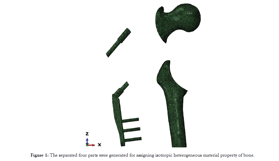
Figure 1: The separated four parts were generated for assigning isotropic heterogeneous material property of bone.
Three INP files were output consisting of nodes and elements of head, shaft and both of them in each of files. Just two of the three files which contained head and shaft separately were assigned, then the material property of head and shaft were input the third INP file using Notepad, respectively. The third INP file that contained nodes, elements and material property of both head and shaft was input as a model in ABAQUS [8]. And the implant was assigned with a Young’s Modulus: 110 GPa and Poisson’s ratio: 0.3 respectively, the material property of the complex was summarized in Table 1. And the isotropic heterogeneous material property of the bone was seen in material property window in Figure 2.
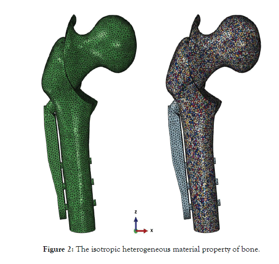
Figure 2: The isotropic heterogeneous material property of bone.
| Components | Young´s Modulus | Poisson´s ratio | Material property |
| Bone | E = 8920ϱ [8] | 0.3 | isotropic heterogeneous |
| Implant | 110Gpa | 0.3 | isotropic homogeneous |
Table 1: Material properties of the complex.
The two segmented parts of implant were merged for one part, and then the relationships of interaction for all parts were performed. The Lag screw and the bone, the cortical screws and the bone, were bonded with nodes. Because the compression screw was fixed the lag screw inside the barrel in CHS system, so for the present study, lag screw and barrel were defined as a bounding relationship. The contact of two interfaces of osteotomy was created with Nonfriction and bonding for simulating two stages of TCVO: Initial post-operative stage and finish of bone healing stage. A static configuration simulating one-leg stance condition for loading and boundary was created. And the distal femoral was constrained. For the purpose of validation of the FEA model, an experiment test was performed with an intact femur under a 2000-N vertical loading on the femoral head, and the displacement at the inferior aspect of the femoral head was measured, compared to the results obtained from the intact FEA femoral model subjected to the loading condition from the report [6].
Evaluation for TCVO model
Max Displacement of the complex, Max von Mises stress for the interfaces and CHS system were analyzed for evaluating the stability and fracture risk in initial post-operation and finish bone-healing stages. There was no need to use statistical approach because of only one sample included.
Displacement of the complex
In this study, we also tested the situation in which the coefficient of friction over interfaces of osteotomy was defined as 0.5 to simulate some stage of bone before healing after the surgery. The results of displacement were displaced in that there was no meaning for the Non-friction stage and 0.5 coefficient friction stage, with the Max displacement: 9.695 mm and 9.355 mm, separately. And a strong decrease with the Max displacement of 3.456 mm in condition of bonding for the interfaces (Figure 3). The evaluation of mechanical parameters was focus on the two conditions for the interfaces with Non-friction and bonding for simulating two stages of TCVO: Initial post-operative stage and bone-healing stage.
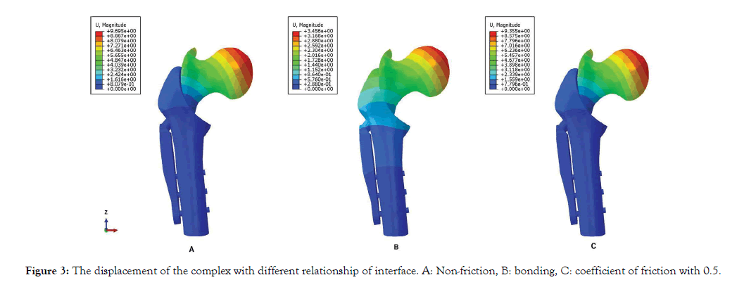
Figure 3: The displacement of the complex with different relationship of interface. A: Non-friction, B: bonding, C: coefficient of friction with 0.5.
The distribution of von Mises stress for the interfaces
The results were displaced in Figure 4. A and C was simulated the initial post-operative stage, the concentration of von Mises stress was present at the area of lag tunnel with the Max values: 122.0Mpa in A and 84.20Mpa in C, comparing to the B and D simulating the bone-healing stage
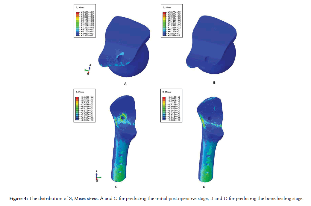
Figure 4: The distribution of S, Mises stress. A and C for predicting the initial post-operative stage, B and D for predicting the bone-healing stage.
With the concentration of von Mises stress in the infero-medial area of contact in the shaft instead of the lag tunnel area with the Max values: 80.95Mpa, which was below to the former simulating.
The distribution of von Mises stress for CHS system
The results can be seen in Figure 5. A, C were simulated the initial post-operative stage, B and D were simulated the bone-healing stage. The concentration of von Mises stress was displaced in the junction of osteotomy for both A with the Max von Mises stress values: 1765Mpa and B with 334Mpa. And the von Mises stress distribution was more averaged on the CHS implant for the bonehealing stage than the initial post-operative stage, in which the same loading condition was performed.
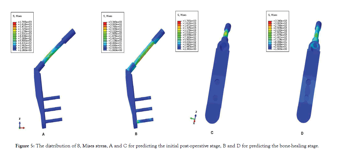
Figure 5: The distribution of S, Mises stress, A and C for predicting the initial post-operative stage, B and D for predicting the bone-healing stage.
The TCVO model fixed with the CHS system was simulated based on FE method. And the mechanical parameters of displacement for evaluation of stability of the complex and the von Mises stress for evaluation of risk of fracture was focused on the interfaces and implant for interpreting the clinical complication that discussed earlier. Meanwhile, two stages were predicted for simulating the initial post-operative phase and bone-healing phase with different interaction relationship over the osteotomy interface. The results were totally different for all the parameters in two stages, that displacement and peak von Mises stress was higher than the bone-healing stage, indicating that the protective management is necessary and important for taking precautions against the complications from initial post-operative phase.
The coefficient of friction for bone to bone was different from literature, Chen et al. applied the coefficient of 0.3 to simulate the proximal femur rotational osteotomy [6], however, Chang et al used the coefficient of 0.46 to an intertrochanteric fracture model [9]. In this study, we just tested non-friction and the coefficient with 0.5 as displaced in (Figures 4, A and C), the Max displacement of head was no difference, the same for other parameters, on other hand, it was noted that the large displacement in the prediction of initial post-operative stage, which was meaningful for explaining the Nonunion reasons in the clinical practice using the displacement evaluation, however, there was a huge decrease of the Max displacement by 64% in bonding TCVO model, which there was no micro-motion in the interfaces. From the observation, we could say that stability of the complex was not only supported by the implant, but the bone itself, that also depends on the processing of bone-healing. For the clinical guideline, it was important to decrease the loading activities in daily life until the bone-healing process finished completely. On the other hand, it would improve the whole stability if the CHS system added a screw above the lag screw position to decrease the motions in the interface and enforce the compression between it for increasing the success rate, which had been indicated by clinical research [4].
The distribution of von Mises stress was different obviously in two stages, A and C for prediction of initial post-operative stage, B and D for bone-healing stage in Figure 4. that the higher stress could be seen around the lag screw tunnel from A and C, the compression screw was fixed in the barrel and the motion was allowed in the interface, leading to the focusing stress present in this area, as a pivot of loading, which could be explained for the Periprosthetic fracture in the initial post-operative period. Because no strong compression or fixation in the interface for balancing the load added from the upper body weight indicating the importance of load-constrained activities in the initial surgery period. And the stress distribution for the prediction of bone-healing stage was distinguished from the former displacing at D and B, which the higher stress area was distributed in the infero-medial contact interface for the prediction of bone-healing stage, which the interfaces were no micro-motion allowed, a strong compression and fixation was available for supporting the load in the interface, and pivot of loading was changed to the infero-medial contact side of interface, which formed a thickened cortical bone this area in long term clinical follow-up observation[3], following the Wolff’s law for bone remodeling, that where the high stress was loaded, where the strength was enforced, the bone remodeling was based on the distribution of stress in the bone.
The distribution of von Mises stress for implant was also followed the mechanical principle consistent with the bone behavior, in the prediction of initial post-operative period, the concentration of stress with a higher magnitude was located in the lag screw where the interface passed, which could be seen in Figure 5,A which was consistent with femur, that could be found in Figure 4, A and C indicating that there was a high fracture risk for the lag screw in this area. However, in the prediction of bone-healing stage, the Max von Mises stress was huge decreased by 81% with a wide area of concentration for the stress, moreover, the high stress was founded in barrel, the intermediate of the plate and the lowest cortical screw in Figure 5, B and D which could provide some mechanical evidence for the metal fracture of clinical complications? From literature, most of the metal used for implant comes from stainless steel that the strength is about 860MPa and yield stress is about 690MPa, which means, the predicted Max von Mises stress of the lag screw has been broken at the case of 25° osteotomy in the initial post-operative stage [10]. The authors added an anti-rotational screw over the lag screw in the initial post-operative stage, the Max von Mises stress decreased to 421MPa, which indicates that the anti-rotational screw is needed or even a must combined with lag screw in such large osteotomy or having a high body-weight patient to prevent the metal fracture [11].
The vital step for the study was to assign the isotropic heterogeneous material property for the bone, which was mapped into mesh element in condition that the position of meshed bone must be the same as the original configuration, which was extracted from Mimics. The more complicated was the two parts of osteotomy could not be assigned at the same time. We needed to integrate the two materials property INP files of separated osteotomy parts into one INP file, manually, for displacing the material property of the two parts at the same time. This was the first time for simulating the TCVO finite element model combined with CHS system, and also the first time for assigning an isotropic heterogeneous material property to the bone of TCVO finite element model.
However, the limitation was not avoided. Firstly, the finite element analysis was a predictive method, in most cases, the validated experiment was necessary to confirm whether the predictive results was acceptable and useful for the research, in this study, the authors just utilized the intact femur for validation and managed the predictive results using finite element analysis to behave the bio-mechanical features of the model. So honestly, it was questioned for the accuracy to some parameters, for example, the Max displacement and Max von Mises stress of the implant, were high, even exceeding the Yield Strength in the prediction of initial post-operative stage, generally, maybe, the real human body could bear such values, even more without destroy the bone quality. And such Max displacement was not realistic because of constraint by soft tissues, maybe, it is reasonable to analysis the trend not the exact values for a meaningful evaluation. Secondly, the simulation of interaction relationship between components, the related importance was to simulate the function of compression screw in the barrel, for the present study, the authors just made the lag screw non-micro motion to the barrel and bone to equalize the effect of compression of screw. Maybe, the further study needed to reach for a relative prediction with more accuracy. Thirdly, only one sample that was 25° was designed for the study, through the varus angulations varied between the data obtained from clinical reports, mean varus angulation was about 25° the range can be from 12° to 46° based on the stages and types, so it will be more meaningful to design different varus angulations in the study in order to quantify the metal fracture risk, ensuring the surgical approach should be different with different lesions for an optimized treatment.
Finally, the conclusion was that the stability evaluated by the displacement and the fracture risk evaluated by the von Mises stress in this study, which was totally different in two predictive stages, it was conformed that there was higher instability and fracture risk in the initial post-operative period with more displacement and higher stress in the concentrated point, however, there was a high fracture risk in the barrel area after the bone-healing process finished. This study could provide some bio-mechanical evidence for the clinical complications, such as Nonunion, Periprosthetic fracture and metal fracture and the bone remodeling followed Wolff ´s Law after the TCVO surgery. On other hand, it was indicated that the load-constrained activities and strong fixation were benefit to decrease the complication and improve the success rate for clinical practice.
Citation: Feng WH, Zhang HH, Tiana TT, Kanga Z (2021) A Finite Element Analysis of Transtrochanteric Curved Varus Osteotomy Combined with Compression Hip Screw System. J Osteopor Phys Act. 9:232. doi: 10.35248/2329-9509.21.9.232
Received: 17-Dec-2020 Accepted: 22-Jan-2021 Published: 29-Jan-2021 , DOI: 10.35248/2329-9509.21.9.232
Copyright: © 2021 Feng WH, et al. This is an open access article distributed under the term of the Creative Commons Attribution License, which permits unrestricted use, distribution, and reproduction in any medium, provided the original work is properly cited.
Sources of funding : No source of Funding.