Advances in Automobile Engineering
Open Access
ISSN: 2167-7670
+44 1300 500008
ISSN: 2167-7670
+44 1300 500008
Research Article - (2015) Volume 4, Issue 2
The aim of this research is to compare which parameters may vary when braking on different Ministry of Transport (MOT) brake testers, such as roller bed brake tester and dynamometric platform. Different types of brake testers have been used and analyzed by the mechanical engineering staffs at the mechanical laboratory at the Miguel Hernández University. It has been analyzed which parameters can vary the result of the brake test, and advances and disadvantages of each brake tester.
<Keywords: Brake tester; Ministry of transport; Variables; Longitudinal braking
To know which parameters influence on the brake measurement on both brake testers, we have to analyze mathematically the brake equations.
Considering:
re=Effective radius of the wheel on rollers
rep=Effective radius of the wheel on flat ground
r2=r3=radius of rollers
M=Sum of moments
Mf=Braking torque applied to the vehicle wheel
Mt=Roller tractor torque, Mt2=Mt3
F2=F3=Roller tractor force
Fr=Frictional force, Fr2=Fr3
μ=Rollers roughness
P=Weight on the wheel
Re=Effective radius of the wheel
Cos θ=Angle between the symmetry axis and the line between wheel-roller centers (Figures 1 and 2).
On roller bank there is not advance so: I.α=0 (1)
Forces and moments acting on the wheel when braking on dynamometric platform:
ΣFx=m.a (2)
−> m.a=Fx – Fr − Ff (3)
Forces on the y axis:
ΣFy=0, 0=P – N, N=P (4)
In Table 1 formulas of the braking torque on dynamometric platform and on roller bed can be compared:
| On roller bank | On dynamometric platform |
|---|---|
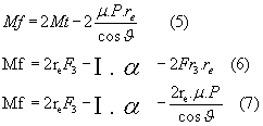 |
Mfp=-Iα+Fx.rep–Fr.rep (9) Mfp=-Iα+Fx.rep–m.P.rep (10) |
 (8) (8) |
 (11) (11) |
Table 1: Formulas of the braking torque on dynamometric platform and on roller bed.
When braking on both testers the wheel should be under the same conditions. Comparing brake torque on dynamometric platform and on roller bed tester formulas we will see the differences
If; Mfr=Mfp, (Subindex r=rollers, p=platform) at constant velocity we have:
2.rerF3-Fr.rer=Fx.rep–Fr.rep −> rer(2F3-Fr3)=rep(Fxp–Frp ) (12)
Or what it is the same;
 (13)
(13)
As we can see, the drag force on the roller is not the same as on level ground, assuming a zero slip, so the braking torque in either case will depend primarily on factors such as:
- The effective radius on flat ground
- The effective radius on rollers.
- Tyre pressure
- Acceleration during the Test
- The separation of the rollers and the cos ϑ
- The weight on wheel
- The adhesion of the wheels on the ground or rollers and the rolling resistance.
The test on the brake roller tester at the MOT center is carried out by placing the vehicle on rollers. The emergency brake should not be actuated. The car stops on the roller bed [4]. Then the rollers rotate at 5 km/h of speed. This velocity is indicated in the “MOT procedure manual” [5] from Ministry of Industry, Tourism and trade of Spain (2014) [6,7]. Brake pedal will be pressed until 100% of slippage is obtained.
The plate brake tester is a method of measuring a vehicles braking system in a dynamic test. It consists of two moving parallel plates mounted on force transducers. Braking force is measured when a vehicle passes over the dynamometric platform and then applies its brakes. The braking action causes the individual plates to ‘slip’ forwards allowing a calculation of braking force to be made. Brake imbalance between right and left hand side can also be measured by the differences in voltage measured on each of the force transducers placed under the chassis. Due to the dynamic operation, plate brake testers are far less common than roller brake testers in Spain MOT facilities.
The vehicle used in the research was a used Renault 21 “Nevada” 7-seater, diesel with a mileage of 90,000 kilometers. It is equipped with front disc brakes with sliding clamps and uses DOT 4 brake fluid with a tandem brake pump. The rear wheels have drum brakes.
To calculate ant slippage, the angular velocity of the rollers and vehicle wheels are measured using two OMRON encoders: the first is fitted to the brake roller tester and the second is in contact with the front, right-hand wheel of the vehicle.
The torque on the rotation axis of the rollers is measured using a strain gauge. The pressure in the brake hydraulic circuit on the right wheel of the vehicle is also measured using a hydraulic sensor in the hydraulic pipe of the right wheel.
Data were recorded using an LMS Pimento portable, multi-channel analyzer.
To ensure that the rotation of the encoders was synchronized with the rollers and the wheel, a spring was placed ensuring good contact.
The slippage on the plate was measured using the following expression:
 (14)
(14)
In Figure 3 the fifth wheel can be seen.
Each of these measurements was obtained by taking the average of ten braking data sets with the same conditions; dispersion of each group of brake measurements was less than 3%.
A comparative analysis was made of the braking measure ments for the same test carried out with different MOT testers, to see differences.
The tree brake testers have different distance between rollers, the same roller diameter and different roller roughness but all of them have the same rejection threshold because the minimum efficiency for all MOT brake testers is 50%. Furthermore, the dynamometric platform has totally different characteristics but also has the same minimum efficiency of 50% as stated in the directive 96/96 CEE [5], and the manual of MOT inspection of vehicles [6].
The efficiency is:
 (15)
(15)
When:
E=% of efficiency, Minimum=50%
Ftotal=Sum of braking forces of all wheels.
m=Maximum permissible vehicle mass in kg
g=Gravity acceleration.
The vehicle breaks 60% with front wheels and 40% with rear wheels. So the mass of the vehicle will be stopped 60% with front wheels and 40% with rear wheels.
Then, the minimum force to pass the MOT test is:

Therefore, the “Rejection threshold” will be 1.8 kN for each front wheel.
In this research it is only studied the right front wheel brake system.
Moreover, it has been demonstrated mathematically that differences between roller testers and dynamometric platform might change brake force measurements. It has been checked if experimental data vary the same way as it is mathematically expected to do [8].
Finally, a vehicle could pass or not the brake test due to the brake tester used. Drivers could choose the MOT brake tester that offer higher probability to pass the brake exam. Therefore, a vehicle with lower brake system conditions could pass the exam and be on the Spanish roads unsafely [9,10].
The measurements obtained from tests were: the brake pressure on the vehicle and the slippage on the braking wheel.
As can be seen in the pictures below, the roughness of rollers at MOT-450 and MOT-410 were the same, 49 microns, while at the MOT- 390 they were lower, 33 microns, because the equipment had been used thousands of times for brake tests in the active period at MOT facilities in Alicante (Figures 3, 4, 5 and 6).
Mot brake testers analyzed were:
• MOT Station 450 from our laboratory at the campus Miguel Hernandez University from Elche, with a distance between rollers of 450 mm.
• MOT Station 410, the city of Elche. The distance between rollers is 410 mm.
• MOT Station 390, located at the Torreblanca building, at Miguel Hernández University from Elche. The distance between rollers is 390 mm.
• Dynamometric platform from our laboratory at the campus Miguel Hernandez University from Elche.
Tests on the four MOTs brake testers were performed with the same Continental Contact tyre, to know that the differences obtained in the measures were not due to this parameter. Tyres were inflated from between 1 and 3 bar (1, 1.5, 2, 2.5 and 3). A comparative analysis was made of the braking and slippage measurements for the same test conditions carried out with different tyre pressures.
Variability of Experimental Data obtained on Roller Bed Brake Tester
The influence of the roughness on the brake data measured has been analyzed by comparing the measurements between MOT-390 and MOT-410. 32%. Lower brake data values were obtained using the MOT-390 using the same Continental Contact tyre. This difference was due to the different distance between rollers and tyre and due to the different roughness of roller surface, 49 μm for MOT 410 and 33 μm at MOT-390. The roughness values were measured with a digital profilometer.
With the same roller diameter and different distance between rollers, (the numerical value after the MOT acronym indicates the roller base in mm), to analyze the influence of this parameter in brake data obtained (Figure 7).
Differences in measurements were obtained due to the decrease of 40 mm of distance between rollers (MOT-450 and MOT-410). The roughness of rollers was the same: 49 μm.
It was observed that the car will pass the test only with tyre pressure higher than 1.5 bar or more at MOT-410, when the brake system is right. However, with the same car and the same tyre it will never pass the test at MOT-390 while it will always pass the test at the MOT-450 tester with any tyre pressure. It has been proven that a vehicle will have the highest possibility of passing the test using the MOT-450 secondly MOT-410, and finally the MOT-390.
We analyzed the influence of increasing the weight on the car by 108 kg on the front axle with 54 kg on each wheel. Brake data was measured with different tyre pressures with the same Continental Contact tyre.
This addition of weight to each wheel on the front axle affects the brake measurements at MOT-450 by between 2.5% with 1 bar tyre pressure and 12% with 2.5 bar tyre pressure. So the more the weight increases so too does the possibility of passing the test, even more so when the tyre pressure increases.
This phenomenon is produced due to the weight on the front axle produces a bigger contact area for friction between the tyre and the roller, therefore that the maximum slip appears later, then more brake torque has to be applied to the wheel to obtain 100% of slippage on the MOT brake tester.
Therefore, the maximum brake value when the maximum slip point is obtained will be higher as the weight increases because the effective radius re will be lower because of the weight on the wheel [11]. If cos θ is higher then brake torque, Mf, to stop the wheel on the rollers will be higher.
Moreover, when the radius decreases because the weight increases, the brake torque to stop the vehicle increases (Figure 8).
To summarize see Table 2.
| Parameters | From 1 to 3 bar tyre pressure |
|---|---|
| Tyre pressure | At MOT-450 maximum difference 8,5% |
| MOT-390 max. difference 41,4% | |
| Rollers roughness | It decreases 27,7 % when it changes from 49 µm to 33 µm |
| MOT wheel base | + 11,6% (1bar) to −1,5% (3bar) Comparing MOT-410 vs MOT-450 |
| Weight increment | +2,5 to +12% increasing +54kg on each wheel. |
Table 2: Percent of variation when parameters studied changed.
Thus, it has been demonstrated that the measure of brake obtained from roller MOT testers depends on the tyre pressure, the distance between rollers, the roughness of rollers and the weight on the wheel. The same vehicle, with the brake system in perfect condition, can pass or fail the brake test, depending on which of the MOT testers were used.
Finally, it can be concluded that these parameters affect the brake measurements at MOT test centers and distort the results of the brake test.
Variability of Data Obtained on a Dynamometric Platform
Through various tests it has been possible to identify the importance of tyre deformation at the contact patch. It is essential to let the tyre tread minimum period to develop and stabilize the deformation in the contact patch and remove the transitional periods. Otherwise, it is not possible to characterize the behavior of the tyre at steady state. Changing the direction of vehicle movement involves changes in the deformation of the contact patch and therefore the forces Fx and Fy.
From the results shown in the previous sections of this article we can conclude that the main variables influencing the longitudinal and transverse forces are:
• The convergence angle,
• Wheel pressure, P
• Vertical force Fz.
It has proven the small influence of variation of parameters such as: camber angle, and the temperature, T, in the registered forces.
Finally, it is important to emphasize the limited influence of speed in the transmission of forces on the tyre-road contact in the range between 0 and 8.4 m/s (0 to 30 km/h), no as for higher speeds, and the importance of conducting a pre-entry plate and adhesion control for variations in the rolling contact surface [8,9].
Comparison between both Measurements
Comparing both measurements, it can be seen in the following figure that brake force to stop the car on a dynamometric platform will be higher than on the roller bank (Figure 9):
After analyzing the banks of brake rollers and dynamometric platform we present a comparative analysis between both systems indicating the advantages and disadvantages of each:
Advantages and disadvantages of both systems are analyzed: On bank of rollers tester the biggest advantage is the ability to maintain the braking of the car for long periods of time to test repeatedly the braking system. It allows determine the ovality and brake roll and can detect and isolate problems “fading” brake overheating causing loss of braking efficiency.
Mechanical problems such as the “ovality” and warping are more easily to be detected on the roller brake tester because the brake with a gradual braking and this does not happen on the dynamometric platform because the braking data are obtained at a certain point.
In the case of a broken damper when measuring on roller bed, it could not be detected because it is only measured the braking system. On a dynamometric platform a problem with the damper would be detected because of the drag of the wheel. Thus, the brake to stop the car would be measured delayed from one wheel to the other. Until the suspension does not reach full compression the vehicle the weight of the wheel will be not transmitted totally to the dynamometric platform. Therefore, to check the braking plates is necessary that the dumpers are in good condition. On the other hand this is not needed on a roller bank because on roller the effectiveness measured is independent of the efficacy of the suspension.
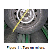
To understand the discrepancy of measurements between roller bed brake tester and dynamometric platform, (with the same tyre and the same wheel inflation pressure and the same load on wheel), it should be analyzed the variation of the tyre contact patch. The tyre contact patch will influence: adhesion, rolling effort, and rolling resistance.
For this study it was used a tyre type: Radial 155/70R13, wheel pressure: 2.3 bar, vehicle used: Ford fiesta. Data results of tyre contact patch on rollers and on a dynamometric platform is shown below in Table 3.
| Contact area (mm2) | |||
|---|---|---|---|
| Roller bed | Area2 = 24.59 mm2 Perimeter = 23.31 mm Area 3 = 23.45 mm2 Perimeter = 21.46 mm Total = 48,04 mm2 Radio of laded wheel: r= 26,6 mm |
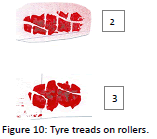 |
 |
| Dynamometric platform | Area 1 = 230.28 mm2 Perimeter = 63.83 mm Radio of laded wheel: R= 26,3 mm |
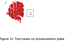 |
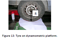 |
Table 3: Area of tyre contact patch on rollers and on a dynamometric platform.
When the car brakes a pitching moment about the center of gravity is generated. Therefore, a load transfer of from the rear axle to the front axle appears. Being the rear axle is lighter than back axle; in addition, because of the vehicle dynamics the rear axle would be downloaded transferring load to the front axle, whenever the brake is operated. This phenomenon depends on the height of the center of gravity of the vehicle and its wheelbase.
Therefore, other weakness of the roller bank tester is the inability to take into account the mass transfer to the front axle that occurs when braking in normal traffic. In other words, the data of the distribution of braking between the axles is not well measured when braking on roller banks.
On the other hand, braking on a dynamometric platform, “ovality”, problems of brakes and disk war page cannot be measured correctly with this tester (Table 4).
| Advantages of the roller bank as a brake tester | Advantages of the dynamometric platform as a brake tester |
|---|---|
| Brake is measurement in static conditions velocity of test cannot vary, 5 km / h. Inertia is no measured. Therefore, this parameter will not vary the measurement. | • The measurement is performed in dynamic (engine of the roller needs the AC and the dynamometric platform does not). • Faster testing. • brake test including inertia. • Checking 4x4. • Check ABS system. • Possibility of testing at different speeds. • Check also dampers condition. |
Table 4: Advantages of a roller bank and a dynamometric platform as a brake tester.
When a vehicle is tested in the MOT facilities an objective brake test would be expected. Therefore, measurements should not be influenced by any other parameter. We only need to know if the brakes are in good condition or not.
The braking state is checked by measuring brake effectiveness. Efficacy must overcome a rejection threshold of 50%, which is the same for all Spanish MOT brake testers independent of the characteristics of the individual MOT brake test used.
We have obtained many experimental data. Each time a parameter influence was studied. According to data obtained, the braking required to stop the wheel increases as tyre pressure increases at whichever MOT brake tester is used, when the same Continental Contact tyre is used.
With a higher tyre pressure, the tyre deforms less so the contact area between the wheel and the roller is lower. With a smaller contact area between the tyre and the rollers a higher torque will be required to stop the wheel on the roller tester and also on a dynamometric platform.
Variation of distance between rollers from 450 mm to 410 mm produces a variation in the measurements gathered by the MOT brake sensor, from 1.4% for 3 bar tyre pressure to 11.6% for 1 bar tyre pressure.
On the other hand it has been demonstrated that variations of angles of the wheel will increase the slippage on rollers and on the dynamometric platform so brake measurements will vary when angles (such as: camber angle, caster angle, alignment toe) vary.
Therefore, it has been demonstrated that depending on other extrinsic factors to the brake system, the vehicle would pass or not the rejection threshold. Moreover it could not pass the test with brakes in good conditions.
Thereby, we can cast doubt on the suitability of a brake roller tester and dynamometric platform to determine whether the brake system is in good condition or not.
Results could be standardized by following these tips:
1. All MOT stations should have the same characteristics. Following this tip variability due to: distance between rollers, roughness, and rollers diameter, will disappear but not variability due to: tyre pressure, weight on wheel, wheel angles etc.
2. The variability of will be eliminated using other type of brake tester using a brake verification system without dragging wheels.
Using a system where there is not slippage between rollers and wheels will be the solution to the variability of brake measurements.
I would like to thank for the grant: “Ayudas para la realización de Proyectos I+D para grupos de investigación emergentes” GV/2015/034.