Advances in Automobile Engineering
Open Access
ISSN: 2167-7670
ISSN: 2167-7670
Research Article - (2022)Volume 11, Issue 2
The commercial automotive industry is one of the biggest and most innovative areas in total industry area. Also the commercial vehicle truck segment plays vital role in countries economic growth and activities. The project is centered on design and analysis of truck load body for low commercial vehicle platform. the different vehicle segments like low commercial, medium and heavy commercial vehicles requires different design of load bodies according to the changing customer requirement. The commercial vehicle like trucks in total comprises chassis and load body as main parts and engine, transmission and other systems are located on it. The load body is the assembly of number of parts and its mountings fitted on the truck chassis with required load body mounting arrangement. The load body parts like floor panel, side walls, tail gate, and sub frame assembly are designed considering rules and regulatory measures. The two different high deck side load body models are designed and modeled using modeling software and then analyzed using finite element analysis software for static structural case. The strength analysis of two designed model is carried out using method of inertia relief analysis with required boundary conditions. The model number 1 confirmed the higher Von Misses stress at certain predefined locations. Further the necessary design modifications are done in model number 2 and it is observed to be safe from Von Misses stress criteria by providing reinforcement brackets, gussets etc.
The automobile industry is a significant lifeline of the country’s economic activity. In the year 2012-2013 the contribution of the transport sector to India’s GDP has increased from 6% to 6.7%. Within this, road transport has increased from 3.9% to 4.9%, being the primary driver of the increase in the transport share [1]. According to the Ministry of Road Transport and Highways the truck population in India grew at a rate of 7% per annum between 2011 and 2013. Around 75% of the trucks on Indian roads are two-axle trucks. So the design engineers in this segment have to perform a lot of design activities to assist or develop number of variants of Truck models with their load bodies for changing customer requirement. The load body is the part or system which is subjected to be in loading condition and it is placed on the chassis with the required load body mounting. Using cleats and U-bolts the load body is attached to the chassis, so that the structure built up can withstand large amount of static and fluctuating stresses. In an automotive vehicle, the load body rest on skeleton of vehicle and the load body is connected with the main frame or skeleton with the side channel weld bracket. The various types of load bodies are there according to the type of use, material to be carried, capacity of loading etc. The main types in general used are High deck side, Low deck side, Flat Bed, Tippers, Haulage, Curtain Siders, Box bodies, Temperature controlled bodies, Road tankers, Luton peak bodies etc. The load Body must withstand all types of loads to which vehicle is supposed to carry like -weight of the vehicle, cargo, goods etc. Since the design of the load body is related with various performance parameters of the vehicle also, the proper balance between the cubic capacities, Weight distribution on chassis Unladen kerb weight and Gross vehicle weight Safety has to be maintained in effective overall vehicle body design. So the load body design plays important role in order to determine the dimensions and basic aesthetics of vehicle .The project is centered on design of load body for Low Commercial Platform Truck .Hence the design engineers have a large role to play to assist this body building segment by giving design recommendations on interface aspects, wherever necessary, in order to ensure the safety and performance levels of vehicles. So the load body is first analyzed for static case applying the service load cases and the highly stressed regions are identified. The necessary modifications in design stage are done to finalize the design.
Problem statement
Design the 5.18 m deck length, high deck side truck load body for low commercial vehicle platform for 3300 mm wheel base and non-sleeper coach cab. Also perform strength analysis of load body for service load case to locate areas of high stresses and further provide necessary design modification to make design safe for given loads.
1. Understand and apply the rules and norms of Vehicle Load Body Design developed by CMVR and ARAI [2].
2. Geometric Modeling of two models of High Deck Side load body assembly in Cero 4.0.
3. A Finite element analysis is proposed to determine the Equivalent Von Misses stress in static condition for designed models using the analysis software ANSYS workbench.
4. Suggest the suitable change in design so that the design of load body is safe from stress point of view in static condition.
Literature review
To understand the problem, get familiar with the research work to be carried and to get insights about what previous studies were carried out a variety of literature is refereed. The overview of the literature referred is as follows,
Krishna et al. worked on design and analysis of truck body for increasing the payload capacity. The stress concentration at truck bodies is reduced by use of beams of uniform strength. The various bodies are created with different loading capacity and analysis is done for optimization also the analytical validation is done [3].
Wang et al. presented structural stability analysis of dump truck body based on ANSYS [1]. They studied a modal analysis and feature buckling analysis of the body structure of dump truck under the unloading situation, and also made a nonlinear analysis under the certain circumstances. Through the ANSYS analysis, the body vibration frequency and buckling modal shape was calculated and figured out, and the design of dump truck body was optimized in order to make sure that the stiffness and stability meet the needs.
Aranha et al. presented design of an aluminum truck body mounted on chassis for dry cargo [4]. They studied the main features and tech- nical requirements from the design of an aluminum truck body mounted on a 3-axle truck, with 23 tons of deadweight (gross weight) and 5.4 m of distance between axes.
Code of practice for construction and approval of truck cabs and truck bodies by Automotive Research Association of India has set up the norms and regulations to design the truck body [2].
Vinjavarapu et al. presented design optimization of tipper truck body [5]. The main points studied were vehicle body weight reduction, determination of the critical point having highest stress and modify the design of tipper body to get an optimized in terms of reducing weight and reducing stresses.
Mahalingam et al. worked on the sub frame of the caterpillar mining truck. The work was related with the evaluation of maximum shear stress, equivalent stress and deflection of the sub frame under maximum load condition. The frame was designed using 3 different materials and the most suitable material is selected with the help of FEA [6].
Ramacharan et al. studied Dump Truck Floor Bed for beams of uniform strength. The floor bed of I section with 20 ton of load carrying capacity is modeled using suitable modeling tool and then further FEM is carried out using suitable FEM package .The main objectives were Design checks like static analysis, Weight optimization and selection of the material for manufacturing of floor bed etc [7].
Nayak et al. studied design and analysis of dumped body [8]. The floor, headboard ,side walls are given loads of 100%, 15%, 15% respectively of the rated pay loads and then analyzed for stresses and deformation.
The results obtained from FEM were studied and are compared with those of rigid body modeling.
Bhaskar et al. studied the Non Linear Structural Analysis of tipper truck load body. The dump truck body is analyzed using ANSYS for structural behavior of the body for actual loads and maximum loads. The stress and deformation are obtained for different load cases like self- weight, Design load of 18,26,30,35 ton [9].
Kumar et al. presented optimization of weight and stress reduction of dump for automotive vehicles. The dump body of the truck is modeled and analyzed for various load cases to investigate the weights in each cases and the stress in static case [10].
Zhe et al. represented strength analysis of the railway truck body based on ANSYS. Special tub shaped structure to carry cargo of railway is designed, the 3D model is prepared. The finite element model of same is prepared with necessary element type, boundary conditions and constraints. The stress of every point everywhere on the structure of the car body is below the yield stress which ensures the safety of the car body during the operation. The simulation results reflect the stress distribution of the whole car body which provides the reference for design and test [11].
Garg et al. presented design optimization of truck body floor for heavy loading . They studied concept of single layer heavy duty floor has been embarked upon with high strength material which will be able to resist severe impact loads and also results in weight reduction with various other advantages. They concluded that a single layer floor can be a replacement of sandwiched floor and can be used in complete range of truck segment where impact loading is done [12].
Design of load body
The design of load body consists of design of its main parts like Head Board, Tail Gate, Side Walls and Floor Panel. All the parts are to be designed considering the loads, functional requirement, and type of application to be used and some of the geometrical parameters of truck chassis. The design includes determination of geometrical parameters, material selection of various parts, three dimensional modeling of parts and its assembly etc.
Design inputs: The design of load body, its components and sub frame is accomplished considering following design inputs [2].
• The deck length should be 5.181 m.
• The load body should be of high deck side type only.
• The body should be designed for truck having 3.3 m wheelbase.
• The body should be designed for non-sleeper coach cab.
• The maximum Rear Over Hang (ROH) should be 60% of the wheelbase or 3.7 meters, whichever is the lesser.
• Once body attached to the chassis the gap between cabin and load body should be 50 mm.
• The maximum height and maximum overall width of load body should be 3.3 meters and 2.5 meters respectively
Selection of material: Material selection is the main or initial step of the design process. The selection is carried out considering the function specification, performance specifications. These material properties have been used as input while performing the static structural analysis. The materials selected are listed below in Table 1.
| Sl. No. | Part Name | Material |
|---|---|---|
| 1 | Floor panel, Side walls, Front wall tail gate | Plane Carbon Steel (7C3): Tensile Strength-320N/mm2; Density-7800kg/m3; Poisson’s Ratio-0.29; Sheet hardness-238(B) |
| 2 | Long runner cross member | Metal Steel: Yield Stress-210GPa; Density-2800kg/m3; Poisson’s Ratio-0.29; Tensile Yield Stress-589GPa |
| 3 | Reinforcement channels | E34: Yield limit-330 Mpa; BSK46 Yield limit-360 Mpa |
Table 1: Material selection type styles.
Geometric modeling of load body: Geometric modeling of the various components of load body and its mountings has been carried out in part mode as 3D models using Creo 4.0. The top down assembly approach is used where assembly design is started at highest level possible and individual parts and subassemblies are called within the assembly environment. The generated CAD model is shown in Figure 1. The dimensional specification is as follows:
• Load capacity of the truck 9650 Kg.
• Deck length (L)-5.2585 m; Width (W)-2.2505 m; Height (H)-2.8738 m; Wheel base (mm)-3.3 m.
• Cubic capacity-0.007579880 m3, Mass Kg-780 Kg
• Area of loading platform-5.3132 m2
• Frame type-ladder type heavy duty frame with riveted/bolted cross members.
Figure 1: Geometric modelling of load body.
Finite element analysis
The Finite Element Analysis is a technique an integral part of Computer Aided Engineering used in analysis of real life problems .The method divides the system into number of small parts called elements, further the governing equations are solved at each nodes and results are retrieved. Here the ANSYS Software is used to simulate the entire problem.
Static structural analysis
To study and predict the behavior of load body at static condition the Static Structural Analysis is useful. The analysis is carried at the Overload conditions only. Once the analysis is done it will help to assist weather the load body will sustain the loads for which it is designed or not. The analysis retrieves result values for stresses, strain, deformation of load body etc. The analysis is carried out for two designs.
Inertia relief analysis: Inertia relief analysis is one of the options that permit to simulate unconstrained structures during a static analysis. A number of applications of the inertia relief method are modeling of an aircraft in flight, an automobile on a test track, or a satellite in space. When we are performing a Static analysis it is assumed that the model contains no mechanisms and model should not move as a rigid body (strain free). If either of those conditions exists during a conventional finite element analysis, the stiffness matrix for the model becomes singular. In this method, the inertia (mass) of the structure is used to resist the applied loadings, that is, an assumption is formed that the structure during a state of static equilibrium even though it is not constrained.
In an inertia relief analysis, the applied loads are balanced by a group of translational and rotational accelerations generated automatically by the software. These accelerations provide forces, distributed over the structure in such a way that the sum of the applied forces on the structure is zero.
Load calculations
The entire analysis is carried out for the overload condition. In order to complete the analysis the loads acting on the load body and its distribution along the Front axle Rear axle are to be known. Hence the Payload 9650 Kg is distributed along the respective axes and the loads are calculated for Rated and Overload condition. Load body model is loaded by static forces from material it carry and it’s self-weight. The load calculations are as shown in Table 2.
|
Rated condition (Kg) | Overload condition (Kg) |
|---|---|---|
| FAW | 6000 | 7337 |
| RAW | 10200 | 13908 |
| GVW | 16200 | 21245 |
| Payload | 9650 | 14524 |
Table 2: Load distribution on front and rear axle.
FEM model
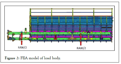
The CAD Model is imported in ANSYS Software and is the modified in Design Modeler of ANSYS Workbench to make it ready for analysis. The respective material properties are applied as mentioned above from material assignment option. Then meshing of the load body is done on the with 3504 number of nodes and 10282 numbers of tetrahedral elements. The inertia relief analysis is carried out by applying the reaction forces at the front and rear axle locations as calculated above. The payload 14524 Kg is modeled using Beam, Shell and Tetrahedron elements. The Finite Element Modeling is shown in Figure 2. The two different designs are evaluated named Design Number 1 and 2 for same loading and boundary conditions but with different design changes.

Figure 2: FEA model of load body.
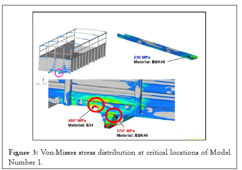
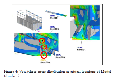
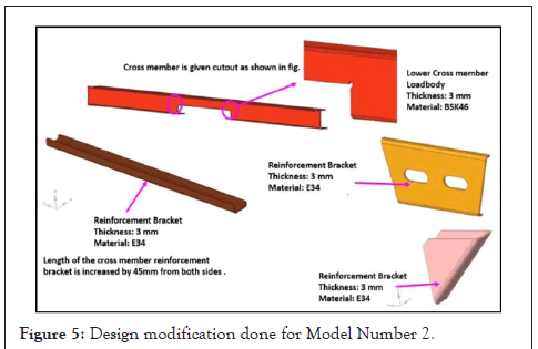
The simulation that was carried out, presented the maximum stresses acting on the components concerning to each of the load cases for two different designs. As example, the Figures 3 and 4, show some results correlated to the Von Misses Stress values of two designs respectively. In the Design Number 1 the observed stress values are 570 MPa and 470 MPa at the bottom of the head board near gussets and the cutout provided at front of load body. These stress values are observed higher than the Material Yield Stress. After making design modifications in Design Number 1, comprising parametric and topological methods, the shapes and dimensions of the cutout and reinforcement brackets, Design Number 2 is analyzed for same boundary and loading condition. The design modifications done are shown in Figure 5.

Figure 3: Von-Misses stress distribution at critical locations of Model Number 1.

Figure 4: Von-Misses stress distribution at critical locations of Model Number 2.

Figure 5: Design modification done for Model Number 2.
The maximum equivalent stress occurred at front side of cross member where the long runner and cross member are connected with gussets. In Design Number 2 the maximum stresses occurring at the critical locations are proved under the material yield limit. The stress values in Design Number 2 at critical locations were 470 MPa and 370 MPa for BSK46 and E43 respectively and these values obtained are below yield limit of material in tension. Table 3 shows summary of stress values obtained in two cases and stress reduction. The stresses at two critical locations for two models are tabulated below, the average 28.4% overall stress reduction is achieved.
| Critical location | Material name & Yield limit (Mpa) | Observed Von Misses Stresses (MPa) | Percentage stress reduction (%) | |
|---|---|---|---|---|
| Design Number 1 | Design Number 2 | |||
| Location 1 | BSK46 (460-560) | 570 | 455 | 20.17 |
| Location 2 | E34 (340) | 490 | 310 | 36.73 |
Table 3: Von Misses stresses at critical locations.
After creating the finite element model, the structural strength analysis of truck load body is done. The obtained Von Misses stresses observed to be higher than yield stress in Design Number 1. So to enhance the stress/strength at weak locations on load body observed in Design Number 1, the few measures like providing cut outs, reinforcement brackets, gussets, angular brackets and necessary design modifications are done in Model Number 2. In the Design Number 2 the generated Von Misses stresses are within the material yield limit so the design is safe. Hence the Design Number 2 is observed to safe from stress point of view in static condition.
I wish to express my sincere thanks to the project guide Professor Dr. M B Mandale and all faculties of Mechanical Department for his support and constant encouragement for this paper.
[Crossref]
Citation: Kulkarni HK, Mandale MB (2022) Design and Analysis of Truck Load Body for Low Commercial Vehicle Platform. Adv Automob Eng. 11:187.
Received: 03-Feb-2022, Manuscript No. AAE-22-5791; Editor assigned: 10-Feb-2022, Pre QC No. AAE-22-5791 (PQ); Reviewed: 24-Feb-2022, QC No. AAE-22-5791; Revised: 03-Mar-2022, Manuscript No. AAE-22-5791 (R); Published: 10-Mar-2022 , DOI: 10.35248/2167-7670.1000187
Copyright: © 2022 Kulkarni HK, et al. This is an open-access article distributed under the terms of the Creative Commons Attribution License, which permits unrestricted use, distribution, and reproduction in any medium, provided the original author and source are credited.