
Journal of Fundamentals of Renewable Energy and Applications
Open Access
ISSN: 2090-4541
+44 1300 500008

ISSN: 2090-4541
+44 1300 500008
Research Article - (2023)Volume 13, Issue 1
Increase in the world energy demand has made renewable energy source as one of the best option. The environmental pollution and rising cost of the fossil fuels have drawn considerable attention to renewable energy sources. Solar energy is one of the major source of renewable energy. As the requirement of the solar energy is increasing day by day for generating electricity, heating purpose, street lighting, solar charging station and in industries, etc. So solar energy is best and more efficient in various application. According to study/data the efficiency of solar panel is about to 16% to 18%, So R and D is going on, how to maximize an efficiency of solar panel by maximizing electricity genration. To increase the efficiency by solar panel we are introducing dual axis solar tracker system. Dual axis solar tracker system we fabricated and do the experimental work, and testing in laboratory, at MIT ADT University. The work of the project focused on hardware design, manufactured part and assembly. As per the testing take place, we compare the single axis solar tracker with dual axis solar tracker, according to readings the dual axis solar tracker is more efficient then single axis solar tracker. This system results in a wide field of view with minimum error effectiveness.
Real time clock; Arduino; Stepper motor; DC motor
In India around 470 million tons coal is used in 2017 by various thermal power stations which produces lots of pollution. The solar tracking system plays a major role in which it is used to capture the maximum power from the sunlight. During those days, the power generation method is not great as now because there are many types of power generation system like nuclear power plant, hydroelectric power plants, geo thermal power plants, other non-renewable and also renewable energy source power generation methods. A new concept for solar detection sensor implementation in photovoltaic dual-axis sun tracker systems. Concept was developed and optimized to maximize the solar panel’s efficiency by tilting the panel to be perpendicular to solar radiation at all times. The effects in efficiency of the proposed system over the fixed 24 W solar panel, The results of which showed a 25% increase in efficiency, high enough to justify implementation as the range for existing systems is 15%-20% [1]. The system is based on a PILOT-PANEL scheme, each equipped with a Light to Frequency Converters (LTF). The advantage of LTF is that its output frequency is proportional to the irradiation which means proportional to power. The PILOT continuously tracks the sun. Every time the PILOT moves to a new position, a microcontroller reads both LTF's frequencies and compares them. If the difference is less than a pre-set value, the PANEL stays in the current position and the PILOT continues its tracking c the difference is bigger than the offset, the PANEL aligns itself with the PILOT.
The purpose of this paper is to simulate and implement the most suitable and efficient control algorithm on the dual axis solar tracker which can rotate in azimuth and elevation direction. The simulation gives the tracker angles that position the solar panel along the sun’s rays such that maximum solar irradiation is absorbed by the panel. It mainly focuses on the design and performance analysis of the various dual axis tracking solar systems proposed in recent years. Although the choice on the use of trackers mainly depends upon the physical features of the land but in general this system has proved to be more efficient and advantageous than its single axis and fixed Counterparts. The selected concept was developed and optimized to maximize the solar panel’s efficiency by tilting the panel to be perpendicular to solar radiation at all times. The system consisted of a solar panel, a stepper motor, a Light Dependent Resistor (LDR) sensor and an arduino mega microcontroller. The output from the LDR sensor determined whether there was sufficient radiation, prompting calculation of the desired tilt angle and subsequently the output speed of the stepper motor [2]. This paper focus on simulate and implement the most suitable and efficient control algorithm on the dualaxis solar tracker which can rotate in azimuth and elevation direction. The simulation gives the tracker angles that position the solar panel along the sun’s rays such that maximum solar irradiation is absorbed by the panel. An automatic microcontroller based solar tracker with a hybrid algorithm for locating the sun's position. The proposed hybrid solar tracking algorithm combines both sensors and mathematical models to determine the precise sun's position, thereby harnessing optimal solar energy for all weather conditions. Experimental results consistently show that the hybrid solar tracking algorithm can yield higher solar power that the traditional active and chronological algorithms [3].
As we fabricated the entire sytem and after placeing the solar panel we take readings in a day from 8 am to 6 pm by comparing with single axis solar panel. According to readings taken the efficiency is calculated and the dual axis solar tracking system is more efficient [4].
Arrangement of base for dual axis solar tracker
• Specifications
• Solar Panel (Havells 100 W polycrystalline panel)
• MS Rectangular coil tube 3 × 1 inch (For frame)
• MS Square plate-300 mm × 300 mm × 5 mm
• Two MS Square plates-200 mm × 200 mm × 4 mm
• Square pipe-100 mm × 100 mm × 3 mm
• 4 Nut bolts-12 mm
• Ball bearings
• Arrangement of spur gear for smooth rotation
As the solar panel is placed on frame and below the frame we had made one arrangement of spur gear for smooth rotation of solar panel in north-south direction and due to the arrangement of spur gear the load acting or weight acting will manage by gears and it reduced the speed of rotation [5].
Governing equation for the analysis
The tracking system must know the sun position in order to follow the sun. There are two methods to track sun in the day time. One is active mode and another one is passive mode. The passive mode is linearity based system. It is purely dependents on sensors output. In this sensor senses the sun’s position at the atmosphere and sends the signal to controlling device. The disadvantage of the linearity based tracking system may affect by the environmental condition and physically. The solar radiation and the angle of solar will change depends on seasonal climates. The maximum solar energy could be yield from concentrators, when the altitude and azimuth angle of concentrators are in solar position. The tracking device is required to place the concentrator at the sun’s position. In order to utilize this solar radiation, it is important to calculate the azimuth and altitude angles [6].
The general solar angle terms are declination angle, azimuth angle, elevation angle, incident angle, zenith angle, hour angle and inclination angle. Figure 1 shows the angle position of the sun.
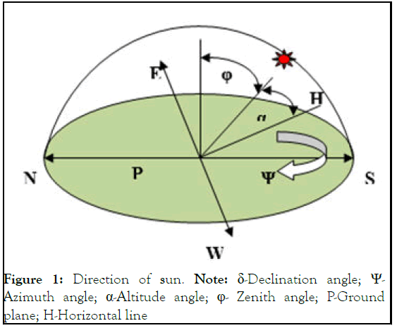
Figure 1: Direction of sun. Note: δ-Declination angle; Ψ- Azimuth angle; α-Altitude angle; φ- Zenith angle; P-Ground plane; H-Horizontal line
The declination angle is represented by δ. Though, the earth rotation is tilted by 23.5° and the range of the declination angle is -23.5° ≤ δ ≤ +23.5°.

where ‘d’ is the day of the year. The solar azimuth angle will vary throughout the day and year. The sun rises from east side and sunset’s west side. The azimuth values are 0° for due north, 90° for due east, 180° for due for due south and 240° for due west. The following Eq. (2) provides the azimuth calculation,

where ’L’ is the latitude (Positive in hemisphere). The vertical angle ‘α’ is denoted as altitude angle. It falls between the of ground plane ‘P’ and sun. The altitude angle is calculated using the following formula:

where ‘H’ is the hour angle. Solar Elevation at Northern hemisphere and southern hemisphere as calculated using the following Eq. (4) and (5)

The solar hour angle will raise 15° by every hour interval. The hour angle will be zero degree at noon time. It can be calculated by the below formula,

The sun rise of an hour angle (Hs) is -180°<Hs<0° and sun set is 0°<Hs<180°.The solar zenith angle (φ) is the angle between sun and the vertical line from the ground plane to the zenith. Summer and winter solstice zenith angle can be calculated using the following Eq. (7) and (8) respectively,

From the above equations we can find the sun’s position in a day. According to the sun’s position equation, the tracker system can able to track the sun [7]. The sun’s position can be programmed into the microcontroller in order to follow the sun. The tracking system will be independent to the linearity system [8].
Description and apparatus
Arduino UNO controller:
• ATMEGA328 P: PU is an 8-bit Microcontroller
• RISC Architecture
• Operating Voltage: 1.8 to 5.5 V
• Input Voltage: 7 to 12 V
• Digital I/O pins: 14
• Flash Memory: 32 k bytes.
• SRAM: 2 KB
• EEPROM: 1 KB
• Clock speed: 16 MHz
Motor 1:
• Type=DC Planetary geared motor
• Torque=40 KG CM
• RPM=10
• Shaft Diameter=10 mm
• Weight=400 g
• Supplier=Hitech electronics
Motor 2:
• Type=Stepper Motor
• Torque=30 KG CM
• Shaft Diameter=6.35 mm
• Step angle=1.8 degree
Driver module:
Type-TB6600 Stepper Motor driver controller • Input current: 0-5 A
• Micro step: 1, 2/A, 2/B, 4, 8, 16, 32.
• Power: 160 W
• Temperature: 10-45 Degrees
Solar panel:
• Rated power (Pmax) Wp=100 W
• Max power voltage (Vmp), V=19.12 V
• Max power current (Imp), A=5.23 A
• Open circuit voltage (Voc), V=22.68 V
• Short circuit current (Isc), A=5.60 A
• Module efficiency (%)=14.90%
• Number of cells=4 × 9
• Module dimensions (mm)=1005 × 668
• Module thickness (mm)=35
• Approximate weight (kg)=9.7
• Ambient temperature °C=-40 to +85
• Hail impact velocity, m/sec=23
• Frame=Silver anodized aluminum alloy
• Solar module price=Rs.5376/-
RTC (Real Time Clock):
• Type-DS1302
• With battery
Calculation of stepper motor:
• Duration of movement: 10 hours=660 min (from 8 am to 6 pm)
• Total angle to be moved: 220 degrees
• For 220 degrees time taken 660 min
• For 1.8 degrees time taken is:

• 1.8 degree is the step angle for our stepper motor.
Comparison between existing and proposed system
As we compare solar panel with dual axis solar tracker in morning 8 am to evening 6 pm, according to reading compare the dual one is more efficient than the fixed solar panel [9]. The solar panel moves in the direction of RTC t and travels in various at Intensities of light in both horizontal and vertical plane with different angles with different times. The important comparison done in below (Figures 2-4 and Table 1) [10].
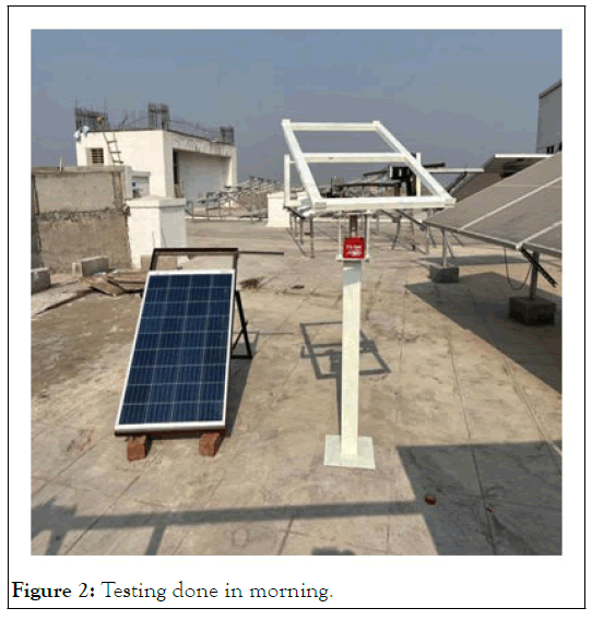
Figure 2: Testing done in morning.
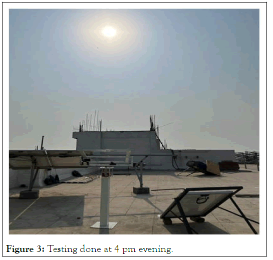
Figure 3: Testing done at 4 pm evening.
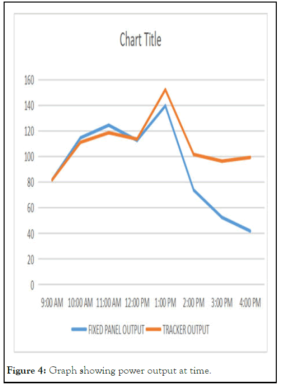
Figure 4: Graph showing power output at time.
| Time | Fixed module | Dual-Axis solar tracker | Power | ||||
|---|---|---|---|---|---|---|---|
| Voltage (V) | Current (I) | Power (Watt) | Voltage (V) | Current (I) | Power (Watt) | % Change | |
| 9 AM | 21 | 3.9 | 81.9 | 21 | 3.9 | 81.9 | 0 |
| 10 AM | 22.7 | 5.05 | 100.16 | 21.8 | 5.1 | 111.18 | 0.11 |
| 11 AM | 22.4 | 5.56 | 86.88 | 22.6 | 5.25 | 118.65 | 0.35 |
| 12 PM | 22.1 | 5.1 | 112.71 | 22.6 | 5.03 | 113.678 | 0.85 |
| 1 PM | 24.5 | 5.7 | 139.65 | 23.8 | 6.4 | 152.32 | 8.3 |
| 2 PM | 22.4 | 3.1 | 73.92 | 22.6 | 4.5 | 101.7 | 37.58 |
| 3 PM | 21.9 | 2.4 | 52.56 | 22.6 | 4.27 | 96.502 | 83.6 |
| 4 PM | 21.5 | 1.95 | 41.92 | 21.7 | 4.58 | 99.386 | 137 |
Table 1: Readings taken while comparing panel.
In this graph shown the x axis is time and y axis is power (watt), The blue line indicate Single axis solar panel and the red line indicate dual axis solar tracker. So we see in graph performance of red line is slightly change from afternoon by 12 pm the major change occur. So the power output is maximum by dual axis solar panel. From the above comparison shows that the dual axis solar tracker systems are more beneficial and low-cost system while comparing with the fixed solar system. There are many other applications that are improvised with the help of Arduino microcontroller by controlling stepper motors. For example, the time taken to change in position of stepper motor in step wise. We use RTC that track the sun in every 5 min a one-step its a 1.8 degree, as this rotates from 8 am to 6 pm and then RTC stop working. So dual axis is more efficient then fixed solar tracking (Figure 5).
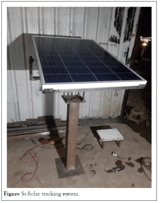
Figure 5: Solar tracking system.
Dual-axis solar trackers are highly efficient in terms of the electrical energy output when compared to the fixed mount system. This prototype can be implemented in large scale for electricity generation. The simplicity, practical, and the effectiveness of the solar tracking system provides a lucrative solution of mobile solar power generation purpose that can be deployed anywhere on the surface of the earth. The manufactured dual axis solar tracking system will increase the Energy efficiency considerably as it tracks the daily as well as the seasonal movements of the sun. Due to increase in efficiency, the size of solar panel and cost of power generation will reduce for the same power generation. In this presented work, the design, implementation and performance of a RTC based dual axis automatic solar tracking system is presented. The performance of the developed system was tested and compared with fixed solar tracking system. This presented work reveal that the RTC based dual axis solar tracking system can assure higher solar thermal generation compared to fixed solar concentrator. The result shows that the real time clock based solar tracking system has 75% more average thermal gain when compared to fixed solar tracking system.
This project has been sponsored by the CRIEYA Department, MIT ADT University, Pune, under CRIYA INNO. PROJECT/ 21/2021. The author sincerely thanks to the CRIEYA department for their valuable support.
Citation: Giri A, Kolte K, Nangar A, Gholap A, Wakhare P, Patunkar P (2023) Design and Fabrication of Dual Axis Solar Tracking System for Performance Enhancement. J Fundam Renewable Energy Appl. 13:304.
Received: 29-Apr-2022, Manuscript No. JFRA-22-17272; Editor assigned: 04-May-2022, Pre QC No. JFRA-22-17272(PQ); Reviewed: 18-May-2022, QC No. JFRA-22-17272; Revised: 05-Apr-2023, Manuscript No. JFRA-22-17272(R); Published: 03-May-2023 , DOI: 10.35248/2090-4541.23.13.304
Copyright: © 2023 Giri A, et al. This is an open-access article distributed under the terms of the Creative Commons Attribution License, which permits unrestricted use, distribution, and reproduction in any medium, provided the original author and source are credited.