Advances in Automobile Engineering
Open Access
ISSN: 2167-7670
ISSN: 2167-7670
Research Article - (2022)Volume 11, Issue 1
Automation plays significant role in keeping welding technology alive for metallic jobs and in tune with today’s demands for productivity, quality weld, lesser resources and cost effective. In addition, the automated welding system ensures the protection of workers from hazards and fatigue. This paper presents the development of Programmable Logic Controller (PLC) based control system for automatic gantry Metal Inert Gas (MIG) welding system with laser seam tracking for alloy steel pipes, plates, etc., The developed PLC control system can control motion of the torch, laser sensor output, arc view camera, welding power source parameters, speed of welding, rotation angle and positioning to preset parameters. Experimental results show that PLC based automatic MIG welding machine improves productivity, weld quality, safety, reduced labor intensity and bring huge economic benefits.
Automatic gantry; MIG; Welding system; PLC; Weld quality
In recent years, most of the manufacturing industries have been switching from the traditional relay logic system to automatic system mainly based on PLC. Since it acts a major function in the automation field, which tends to reduce the complexity, repeatability at higher speed, increases safety and cost efficient. The aim of this project is to develop a PLC based control system for automatic gantry metal inert gas (MIG) welding system that handles the job and welds accordingly up to a joint path [1].
Manual welding has many disadvantages like high labor skill, low productive efficiency and low quality which leads to rework i.e. weld problems like cracks, lack of penetration, lack of fusion, heat affected zone, porosity etc. The welding process emits ultraviolet radiation, sparks and smoke makes the hazardous to environment as well as unsafe to the operator. In addition, handling of job is a major risk during welding. To overcome of these difficulties, PLC based automatic gantry MIG welding system is developed for handling and welding the alloy steel pipes, plates, etc.
Description of the gantry MIG welding system
A system that used for automatic MIG welding is fully controlled by the “SIEMENS 1200 PLC”, which acts as the heart of the system. The sequence of operation was designed using” ladder diagram”. In addition, the PLC controller receives inputs from field elements in its various operational states as well as input from HMI and generates output to control welding power source, servo drive and laser sensor.
Developed automatic MIG welding machine as shown in Figure 1, consists of welding power source, wire feeder, auto control system, welding carrier, job, chuck, etc. Laser sensor is used for seam tracking. It collects the information about work piece geometry and relative position of torch with respect to work piece. It also detects root weld gap, groove angle and centerline detection. PLC will receive the output of laser sensor and pass the information to control system that automatically position the welding torch and do welding [2].
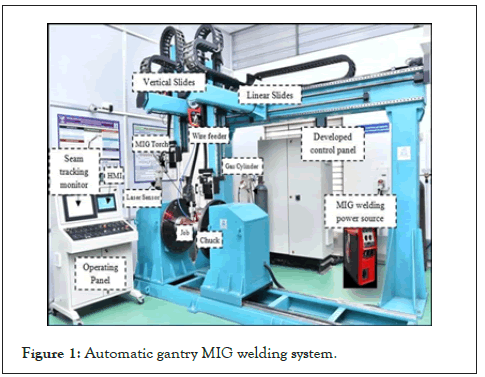
Figure 1: Automatic gantry MIG welding system.
Process of automatic gantry MIG welding system
The Automatic MIG welding system welds the job based on the instructions from PLC. Instructions to the PLC are drawn from Graphic User Interface (GUI), which is entered by the operator based on the weld requirements. Generally, the operation of MIG welding machine consists of three important steps. They are
• Job positioning and clamping
• Torch adjustment and wire feeding
• Seam tracking and welding
Process of automatic gantry MIG welding system is shown in Figure 2.
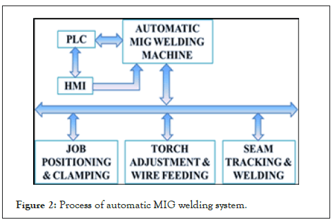
Figure 2: Process of automatic MIG welding system.
Job positioning and clamping
In this automatic welding system, the positioning and clamping mechanism consists of chuck, which is coupled with servomotor. Servomotor helps to give the digital output and speed variation as per the programmable logic controller as it is coupled with chuck. In addition, the rotation of the speed can be viewed in HMI in terms of degree/rpm [3].
Torch adjustment and wire feeding
Water cooled MIG torch is mounted on a square block, which is supported with the column and boom. On the same square block, there is a wire-feeding unit feeding of filler wire. Servomotor is provided at the top of arrangement. By using the servomotor, the height of the MIG torch is adjustable, according to the requirement of job position. This assembly is also capable of moving horizontally and vertically.
Seam tracking and welding
Seam tracking, also known as joint tracking using laser sensor. This process involves a real-time tracking just ahead of where the weld is being deposited. This allows for not only machine trajectory shifts it also provides the feedback to the PLC for controlling.
Welding involves joining of two metals by using high heat to melt the parts together and allowing them to cool causing fusion. In MIG welding, shielding gas (Argon, Co2, Helium, Mixture etc.,) has been supplied along with the filler wire to obtain better quality of welding.
Architecture of PLC based control system
The basic architecture of a PLC based control system consists of main components like PLC, servo drives, relay unit, HMI, MIG welding power source and I/O modules.
The PLC module consists of the Central Processing Unit (CPU) and memory [4]. In addition to a microprocessor, the PLC also contains at least an interface to a programming device and may contain interfaces to remote I/O and other communication networks. The types of I/O modules include discrete (on/off), analog, sensors and special modules like motion control or high-speed counters. The field devices are connected to the I/O modules. The developed control system architecture is shown in Figure 3.
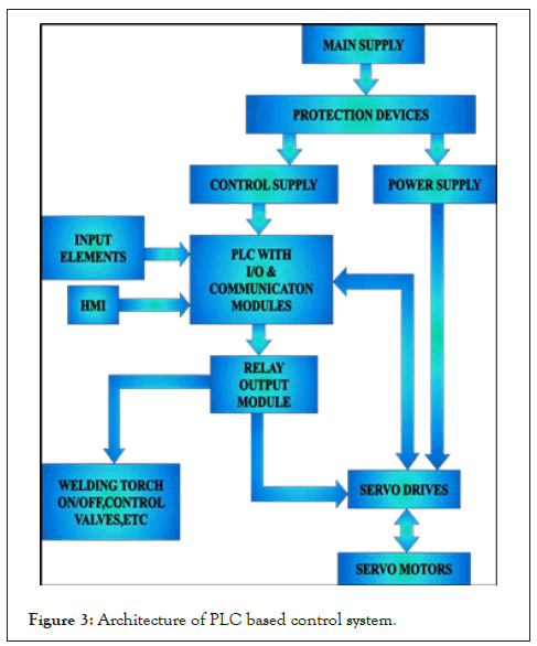
Figure 3: Architecture of PLC based control system.
Control system hardware design
Control system hardware consists of the following main components. The developed PLC based control system was shown in Figure 4.
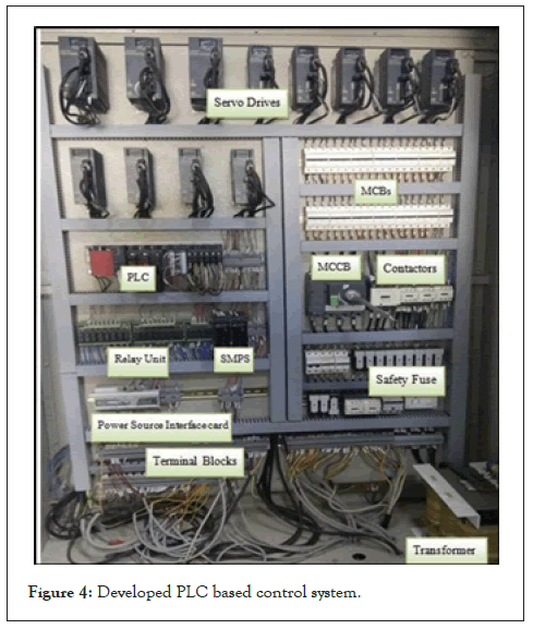
Figure 4: Developed PLC based control system.
Circuit breaker: A circuit breaker is an automatic circuit protection system. Breakers are installed in an electrical panel (breaker box) and each circuit is attached to a singular breaker. The breaker will monitor the circuit and in the event of a complication such as an overload, the breaker will immediately shut off that circuit. This is often colloquially called a “breaker trip” or “tripping a breaker” and it commonly happens when appliances or equipment acts up or too many high-power draw tools are placed (plugged into) a single circuit. There are two types of breakers are using in this control system i.e. MCCB and MCBs.
SMPS (Switched Mode Power Supply): It converts input supply drawn from the AC mains; the input voltage is first rectified and filtered using a capacitor. Here the 230 V AC supply is converted into 24 V DC supply by using SMPS. This will power the Input and Output control devices in the controller.
PLC: A programmable logic controller is a digital computer used for automation of typical industrial electro-mechanical processes such as control of machinery on factory assembly lines, amusement rides, or light fixtures. PLCs are designed for multiple arrangements of digital and analog inputs and outputs, extended temperature ranges, immunity to electrical noise and resistance to vibration and impact. Early PLCs were designed to replace relay logic systems. These PLCs were programmed in ladder logic, which strongly resembles a schematic diagram of relay logic. This program notation was chosen to reduce training demands for the existing technicians. It is heart of an auto MIG welding machine. The data from HMI and field inputs are compiled in PLC as comparison with sequence of operation already loaded in the CPU. In addition, all the operations are controlled and executed through it from the start of welding until the end.
Transformer: A transformer is a static electrical device that transfers electrical energy between two or more circuits through electromagnetic induction. A varying current in one coil of the transformer produces a varying magnetic field, which in turn induces a varying electromotive force (emf) or "voltage" in a second coil. Power can be transferred between the two coils, without a metallic connection between the two circuits. Transformer is used to increase or decrease the alternating voltages in electric power circuit.
Human Machine Interface (HMI): PLC control system for an actual value, in addition to hardware and software, there should be suitable for the user easy operation and of human-machine interface. HMI design quality, directly affect the users of the software product evaluation, thus affecting the competitiveness of the software product. The HMI includes the electronics required to signal and control the state of industrial automation equipment. These interface products can range from a basic LED status indicator to a 20-inch TFT (Thin Film Transistor) panel with touch screen interface. This machine consists of a touch screen with alpha numeric keypad provided over it.
HMI is connected with PLC through Ethernet communication. Therefore, the data, which is entered in the HMI, is directly saved in PLC. In this machine, HMI have welcome screen, parameter settings screen, alarm screen. It is mainly used to set control parameter, starting and stopping the machine, real-time data display, work status displays and fault information display. Figures 5 and 6 gives the HMI screens of developed control system [5].

Figure 5: Parameter settings screen.
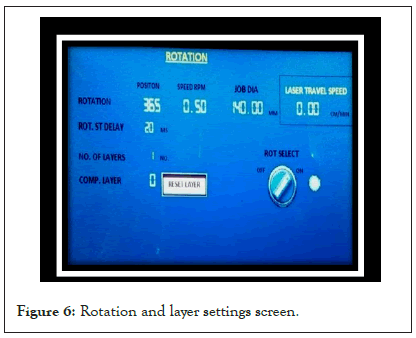
Figure 6: Rotation and layer settings screen.
Relay board: A relay board is a device that consists of a number of relays that are mounted in control panel. A relay is a switch that utilizes an armature powered by an electromagnet in order to complete an electrical circuit. Relays are commonly used to operate the circuits that provide power to motors and lights. Relays are simple devices that are comprised of four basic components. Relays make use of an electromagnet, a spring and a set of electrical contacts, which are connected to an armature. Without power to operate the electromagnet, the armature is held in position by the spring, which keeps it from making contact with the second electrical circuit that it is designed to operate.
Input devices: The devices, which are used to input the data and the programs in the controller known as "Input Devices”. Input device can read data and convert them to a form that a controller can use. Output device can produce the final product of machine processing into a form usable by humans for welding application. It provides human to machine communication. Some of the I/O elements are given below:
• Limit switches
• Push buttons
• Emergency switches
• ON/OFF switches
• Laser sensor
• Proximity sensors
Servo drive: A servo drive receives a command signal from a control system, amplifies the signal, and transmits electric current to a servomotor in order to produce motion proportional to the command signal. Typically, the command signal represents a desired velocity, but can also represent a desired torque or position. An encoder attached to the servo motor reports the motor's actual status back to the servo drive. The servo drive then compares the motor actual status with the commanded motor status. Then it alters the voltage frequency or pulse width to the motor to correct for any deviation from the commanded status [6].
Servo motors: A servomotor is a rotary actuator that allows for precise control of angular position, velocity and acceleration. It consists of a suitable motor coupled to a sensor for position feedback. It also requires a relatively sophisticated controller, often a dedicated module designed specifically for use with servomotors. Servomotors are not a specific class of motor although the term servomotor is often used to refer to a motor suitable for use in a closed loop control system. In the auto MIG there are five servomotors are used, three for major axis motion and two for minor axis motion for both left and right side torches. As it can provides variation in the speed during the operation according to the requirement that is why it is more useful.
MIG welding power source: MIG is a power source, which is used to supply power to the welding. FRONIUS (TPS-400i) power source shown in Figure 7 is used in automatic MIG welding machine. The positive terminal of which is connected to the MIG torch while the negative terminal is connected to the work piece. It is connected to PLC to control the welding as per the programming in it.
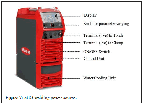
Figure 7: MIG welding power source.
It has digital display screen over which we can see the voltage and current during the welding. Automatic-cooling shutdown is available in it. In addition, we can able to set post flow gas time depend on the welding current [7].
Program sequence: The automatic MIG welding control system has two modes: manual and automatic.
• In the manual mode, by pressing a certain switch the operator can control the welding torch up, down, forward, backward and the workpiece rotation direction.
• In Automatic mode, initially the operator fixes the work- piece or job on the chuck and moves the torch to a specified welding path.
• Select the linear or rotary job according to the requirement.
• For linear welding, enter the length of the weld path/weld length and for rotary welding, enter the rotation angle.
• Enter the welding parameters such as speed of welding, current, voltage, number of layers, delay time for every operation, etc.,
• Then press auto switch, machines works in auto mode for automatic welding operation.
• Through the welding gun, welding wire was melted and the molten material that will deposit on the base material for joining the gap the shielding gas is provided with the filler wire for quality welding.
• Laser seam tracking sensor is also mounted on the torch for tracing the width and depth of the groove. It will give the feedback to the PLC.
• PLC receives the laser sensor input and automatically adjusts the torch position and other settings for maintaining the arc gap as well as groove filling.
• After welding completion, the power source automatically stops process.
• Same sequence continued for further process. Automatic welding machine’s system flow chart is shown in Figure 8.
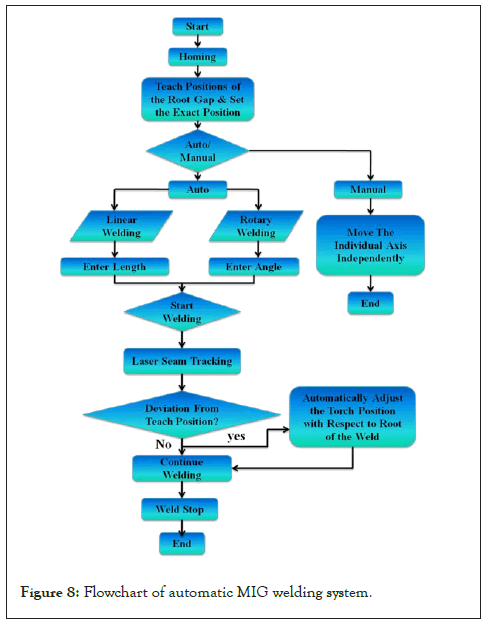
Figure 8: Flowchart of automatic MIG welding system.
The manual welding process has lot many limitations and disadvantages like less productivity, inconsistence quality of welding, dimensional inaccuracy, hazardous to human welders and dependency on operators to large extent. All these disadvantages are overcome by PLC Based Automatic welding system. The system works during normal operation and greatly improved the automation processes with the use of the PLC. The wiring an installation procedure are also improved because the PLC input and output devices are assigned with specific addresses, and thus; further simplifies troubleshooting. Cost reduction mainly on the labor. Hence, only one or two personnel are needed for the operation and maintenance with the automation system. Industries are acquainted by welding automation will find many applications in several industries in coming decades. The use of PLC for controlling action of the automatic MIG welding system effectively results in increased production, less time consumption for welding, quality weld, less power consumption, better safety to the employees and there is no rewiring required in case of any alteration in control action.
Citation: Prabhakaran S, Vinod B, Suresh S (2022) Development of Automatic Gantry Metal Inert Gas Welding System. Adv Automob Eng. 11:182.
Received: 31-Dec-2021, Manuscript No. aae-22-45680; Editor assigned: 03-Jan-2022, Pre QC No. aae-22-45680 (PQ); Reviewed: 17-Jan-2022, QC No. aae-22-45680; Revised: 21-Jan-2022, Manuscript No. aae-22-45680 (R); Published: 28-Jan-2022 , DOI: 10.35248/2167-7670.1000182
Copyright: © 2022 Prabhakaran S, et al. This is an open-access article distributed under the terms of the Creative Commons Attribution License, which permits unrestricted use, distribution, and reproduction in any medium, provided the original author and source are credited.