Advances in Automobile Engineering
Open Access
ISSN: 2167-7670
ISSN: 2167-7670
Research Article - (2017) Volume 0, Issue 0
This paper mainly concentrates on pre-combustion process to increase fuel burning efficiency, decreases fuel consumption and to reduce exhaust pollutants. In the experiment comprises the use of permanent magnets (Neodymium) with different intensities (4000 and 8000 gauss) in the fuel flow line before the carburetor. Hydro carbon fuels are initially in Para state and cluster structure has more intermolecular force of attraction. So, it has fewer tendencies to interlock with oxygen molecules. By providing magnetic field these changes to Ortho state which has less intermolecular forces hence fuel particles are finely divided which results better atomization producing a more complete burn. It has been practically tested and for the purpose of comparing results necessitated to conduct the experiment with and without use of magnets. It was found that the percentages of exhaust components (CO2, HC and NO) are decreased by 30.57%, 97% and 36.08% respectively and carbon monoxide (CO) is increased by 30.57% at 8000 gauss. It means internal combustion engines getting maximum energy per specific volume as well as reduces pollutants to lowest possible level.
<Keywords: Pre-combustion process; Magnetic field; Carburetor; Para state; Ortho state; Thermal efficiency; Pollutants
The hydro carbon fuels used as the prime-mover in the internal combustion Engines, i.e., Petrol and diesel are fossil fuels and fall under the category of non- renewable sources of energy. Studies proved that the aggravated use of these would lead to their extinction in the nearer decades. Moreover, their extended use leads to the atmospheric pollution through the toxic emissions from the exhaust, thus, the global warming and the ozone layer depletion. So, in order to reduce these exhaust pollutants, proper combustion of the fuel is necessary. Though there is no IC Engine that can give out 100% combusted products, the combustion efficiency can be improved by the Pre-Combustion Treatment Of The Fuel, using the energy of the magnets.
Pre-combustion process
Fuels are having hydro-carbons. They are in covalent bond in crystal structure. In that, hydrogen has di-pole moment. Hydrogen can occur in two isometric forms.
These are: 1) Para state
2) Ortho state
Electrons have ability to store energy with in itself. Similar to fly wheel called spin (+1/2,-1/2). Para state has opposite spin and ortho state had same spin. So Para State is less reactive where as Ortho state is more reactive. Initially hydro-carbons present in the fuel are in para state which has more intermolecular force of attraction. So fuel particles are not actively interlocks with oxygen which leads to incomplete combustion. To reduce incomplete combustion there should be a good interaction between the oxygen and hydro-carbons. To attain good interaction the Para state of hydro-carbons are changed to ortho state by applying the magnetic field around the fuel line before entering the carburetor [1].
Reaction with magnetic field
When spin provides small amount of magnetic field, electrons absorbs the energy and properties and changed. The properties may changed and explain by these theories.
1) Chemistry theory (Covalent bond {C=H bond})
2) Physics theory (Barnett effect)
3) Math’s theory (Quantum theory)
Chemistry theory
Each electron has two moments spin moment and orbital moment which maintains uniform fuel structure. Since electrons are having tendency to attract towards nucleus. Due to which intermolecular force of attraction increases. We apply magnetic field around fuel inlet line, intermolecular force of attraction on nucleus which results in better combustion (Figures 1 and 2) [2].
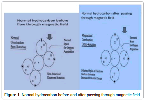
Figure 1: Normal hydrocarbon before and after passing through magnetic field.
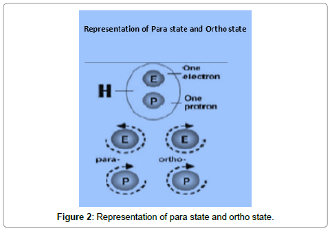
Figure 2: Representation of para state and ortho state.
Physics theory
Spin electrons absorb energy which are in the form of Para magnetic and di-magnetic in nature. Para magnetic electrons attracts high magnetic zone. Whereas di-magnetic electrons are attracts tords weak magnetic zone.
1) Para magnetic substances are O2 and air.
2) Di-magnetic substances are N2 and CO2
The eperiment has been conducted in an appropriate sequence and a well standardized setup. The description of the equipment and the magnetic field used along with the structured procedure.
Magnetic field
To provided magnetic field by two methods. These are 1) Electro magnets 2) Permanent magnets. In this experiment we use neodymium magnets as permanent magnets to provide magnetic field. Permanent magnets are basically classified as Neodymium Magnets and Ferrite magnets [3].
Neodymium magnets (NdFeB): These chemical formulae are N2dFe14 which are in the tetragonal crystalline structure and these are most widely used type of rare earth magnet. These are made from the alloy of neodymium, iron and boron and are considered to be the strongest magnet type among other permanent magnet.
Engine
A four-stroke petrol engine from the Briggs and Stratton make (20S232 0036-F1 series) with a capacity of 10 HP, 305 cc and maximum speed of 3800 rpm, overhead valve intek was selected, as an experimental consideration.
Fuel
The fuel (Petrol) which is provided by the regular petrol filling stations to the cars and two wheelers was used in the experiment. The density of the fuel used is approximately 770 kg/m3 and of the unleaded regular type [4].
Procedure
The setup shown below gives the position of the magnets along the fuel line. The setup begins with the fuel tank, from where the fuel gets filtered in the fuel filter and before it enters the engine for combustion, it passes through the set of magnets placed in the fuel line, thus undergoing pre combustion treatment due to magnetic affect. The exhaust pipe is connected to the gas analyzer, where the quantities of the pollutants like NOx, CO, and CO2 are determined (Figures 3).
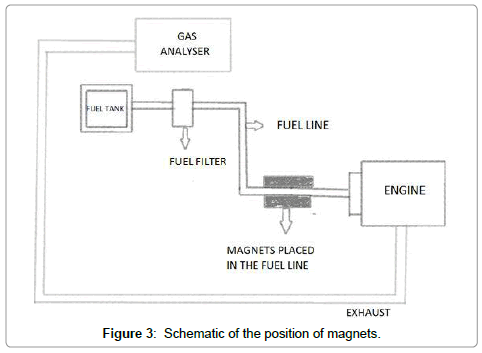
Figure 3: Schematic of the position of magnets.
After the results with two different magnetic intensities (4000 and 8000 gauss) are obtained, then magnetic field has removed, and the exhaust emissions are again analyzed for the pollutants using the gas analyzer. The magnets are placed in radial position to the fuel line and tested at three different speeds (3000 rpm, 2500 rpm and 2000 rpm) (Figure 4).
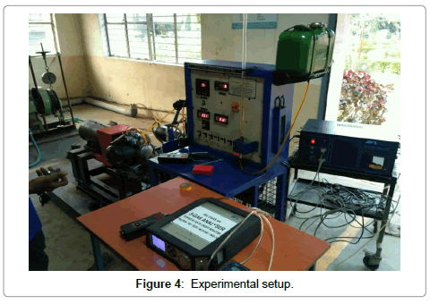
Figure 4: Experimental setup.
At 2000 r.p.m. charge is lean mixture. So, more oxygen is availed at exhaust emissions. It seen to be fuels are not actively bond with oxygen. By using magnetic field emitted oxygen is reduced. It means more oxygen bond with fuel. So, combustion rate is improved. Graphs shows that rich mixture has high amount of hydro carbons in emissions (Figure 5 and Table 1) [5,6].
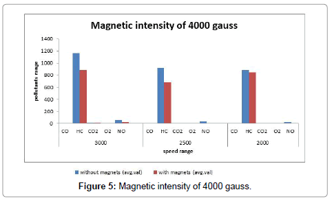
Figure 5: Magnetic intensity of 4000 gauss.
| Serial No. | Speed | Pollutant (Units) | Without Magnet (avg. val) | With Magnet (avg. val) |
|---|---|---|---|---|
| 1 | 3000 | CO % w/vol | 3.88 | 4.75 |
| 2 | HC ppm | 1162 | 887 | |
| 3 | CO2 % w/vol | 8.5 | 8.1 | |
| 4 | O2 % w/vol | 5.38 | 5.17 | |
| 5 | NO % w/vol | 53 | 20 | |
| 1 | 2500 | CO % w/vol | 3.49 | 4.5 |
| 2 | HC ppm | 922 | 682 | |
| 3 | CO2 % w/vol | 7.7 | 7.3 | |
| 4 | O2 % w/vol | 6.8 | 6.44 | |
| 5 | NO % w/vol | 32 | 7 | |
| 1 | 2000 | CO % w/vol | 3.1 | 5.14 |
| 2 | HC ppm | 883 | 847 | |
| 3 | CO2 % w/vol | 7.5 | 7 | |
| 4 | O2 % w/vol | 7.9 | 6.26 | |
| 5 | NO % w/vol | 21 | 4 |
Table 1: Results when magnetic intensity of 4000 Gauss (HC in ppm; CO, CO2, O2, NO in %w/v).
Tabulation results for pollutants when magnetic intensity of 8000 gauss: (Figure 6 and Table 2).
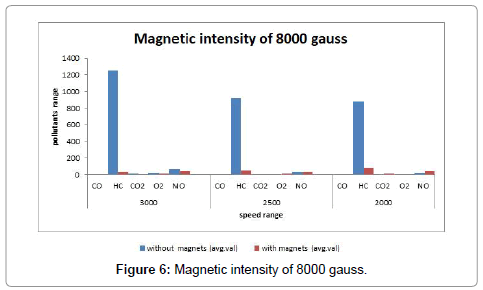
Figure 6: Magnetic intensity of 8000 gauss.
| Serial No. | Speed | Pollutant (Units) | Without Magnet (avg. val) | With Magnet (avg. val) |
|---|---|---|---|---|
| 1 | 3000 | CO % w/vol | 1.57 | 2.05 |
| 2 | HC ppm | 1250 | 36 | |
| 3 | CO2 % w/vol | 9.7 | 6.2 | |
| 4 | O2 % w/vol | 20.27 | 9 | |
| 5 | NO % w/vol | 70 | 42 | |
| 1 | 2500 | CO % w/vol | 3.49 | 3.9 |
| 2 | HC ppm | 922 | 54 | |
| 3 | CO2 % w/vol | 7.7 | 6.3 | |
| 4 | O2 % w/vol | 6.8 | 10.03 | |
| 5 | NO % w/vol | 32 | 35 | |
| 1 | 2000 | CO % w/vol | 3.1 | 4.6 |
| 2 | HC ppm | 883 | 83 | |
| 3 | CO2 % w/vol | 7.5 | 8.6 | |
| 4 | O2 % w/vol | 7.9 | 6.91 | |
| 5 | NO % w/vol | 21 | 44 |
Table 2: Results when magnetic intensity of 8000 Gauss (HC in ppm; CO, CO2, O2, NO in %w/v).
In low speeds % of NO released is more while using the magnetic field but it shows good results at high speeds. At 8000 gauss HC is drastically reduced to minimum level but CO% are increases in all loading conditions. (Figure 7).
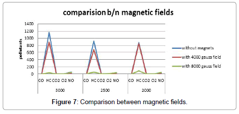
Figure 7: Comparison between magnetic fields.
As per graphs for this engine 8000 gauss magnetic field is more suitable. 8000 gauss field is influences in all loading conditions. It has been observed that at 8000 gauss unburnt fuels (HC) are not more than 100 ppm. It seen to be good combustion. So, more energy produced per given specific volume and pollutants rate is decreased.
With the increase in speed, the percentages of exhaust components (CO2, HC) are decreased by 30.57%, 97% respectively and carbon monoxide (CO) is increased by 30.57% at 8000 gauss magnetic field and concluded that for this capacity 8000 gauss filed is more suitable than 4000 gauss magnetic field. These two pollutants (CO2, HC) are the more harmful to environment and thus, the effect of magnets was positive in decreasing them. Hence, this method can be employed in the everyday scenario of automobiles.
Moreover, in this process, it can be observed that the amount of oxygen emerging out in the form of exhaust decreased at the maximum speed and there are variations in this range from the least to the intermediate. Thus, it can be concluded that there is effective utilization of the oxygen in the internal combustion at the highest speed, and reduction in the pollutants in the exhaust, which is the main objective.