Journal of Aeronautics & Aerospace Engineering
Open Access
ISSN: 2168-9792
ISSN: 2168-9792
Research - (2019)Volume 8, Issue 1
The aim of this paper is to analyze flow in a rocket nozzle and perform FSI simulation for the thermo-mechanical interaction between fluid and solid structure. The nozzle is most important part of the rocket. The proper design plays a major role in the performance of the nozzle, which is designed aerodynamically while considering NPR values. Nozzle is made with Rhenium and coated with Iridium. High speed flow through Convergent-Divergent nozzle leads to complex loading on surrounding structures. The two different cases are carried out and assist the thermal loading on surrounding structures. Structure Interaction analysis is carried in Star CCM+ by creating three different regions i.e., Fluid, Iridium coating (Solid region of 50 μm) and Rhenium structure (Solid region of 1mm) and this analysis gives a better understanding of the behavior of the thermo-mechanical interaction between solid to fluid regions.
A convergent-divergent nozzle is most important component of the rocket engine and it is a combustion chamber extension [1]. The main role of nozzle is to expand and accelerate the gas. The rocket nozzle is designed to control the direction and it is like tube shaped through which hot gases flow. Nozzles are frequently used to control the rate of flow, flow direction, and the pressure of the stream that emerges from them. Size and shape of nozzle depends on mission of the rocket and its application. Nozzle are used even in the turbojet and ramjet engine. During engine startup and shutdown of the rocket nozzle will operate an over expanded mode where the ambient/operating pressure is greater than the internal pressure acting on nozzle wall [2,3]. In nozzle, the flow first converges down to the throat or minimum area of nozzle and then it is expanded through the divergent section to the exit.
The nozzle is exposed to high temperature and it should be coated in order to prevent the complex thermal loading on surrounding structures [4]. The coating is made with Iridium hence its capable of manage the thermal loads and at same time, which needs to be lighter in the weight in order to maximize the rocket lift capacity. Nozzle play a vital role in determine operating characteristics of a rocket engine. A computational prediction of nozzle flow parameter is main objective this paper.
The rocket nozzle dimension as shown in Table 1 is used for CFD modelling. Figure 1 shows overall Dimension of convergent-divergent nozzle [5-7]. Three regions are created i.e., Fluid, Iridium coating (Solid region of 50 μm) and Rhenium structure (Solid region of 1 mm). For solid regions (Iridium coating and Rhenium) created two physics and applied respective material [8,9]. Figure 2 shows the region or material nomenclature of Nozzle, which is modelled in Star CCM+. Interface has been created between regions by selecting common surface from each region [10-13].
| Geometry details | |
|---|---|
| Overall length (L) | 27.3 mm |
| Inlet diameter (Di) | 5.2 mm |
| Throat diameter (Dt) | 2.25 mm |
| Exit diameter (De) | 15 mm |
Table 1: Geometry details of nozzle.
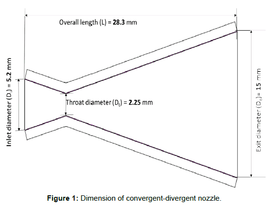
Figure 1: Dimension of convergent-divergent nozzle.
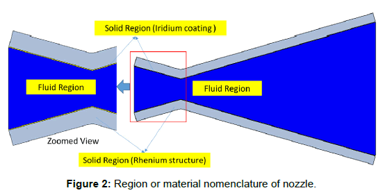
Figure 2: Region or material nomenclature of nozzle.
Polyhedral and trimmer mesh has generated for one case and conducted the simulation for Nozzle. Wall treatment is taken care into account and generated desired prism layer for the both type of mesh. Results from these two type of mesh are same results. Further simulation has been carried for polyhedral mesh since cell count is lesser than the trimmer mesh. Figure 3 shows the cut-section of polyhedral mesh on convergent-divergent nozzle. Total cell count is around 2 million for polyhedral mesh. Two cases has been conducted, which is shown in below Table 2.
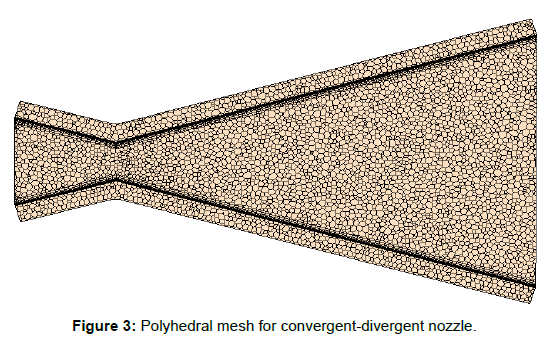
Figure 3: Polyhedral mesh for convergent-divergent nozzle.
| Cases | Pressure inlet | Total temperature |
|---|---|---|
| Case 1 | 16 bar | 1186 K |
| Case 2 | 16 bar | 2276 K |
Table 2: Boundary condition.
3D modelling is done and performed the CFD analysis. The desired number of iterations given and then launched the simulation. Convergence is achieved within the 1500 iteration, which is shown in the Figures 4 and 5. Examined Nozzle temperature profile on solid wall [14]. Assisted thermal loading on surrounding structures with Iridium coating. Iridium coating reduce the thermal loading on surrounding structures and prevent from damage [15]. Figures 5-10 are for the case 1.
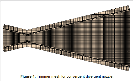
Figure 4: Trimmer mesh for convergent-divergent nozzle.
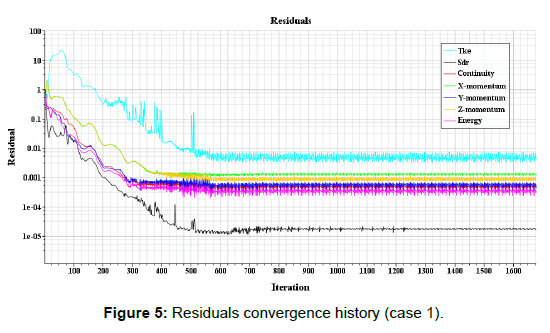
Figure 5: Residuals convergence history (case 1).
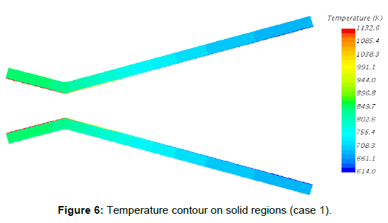
Figure 6: Temperature contour on solid regions (case 1).
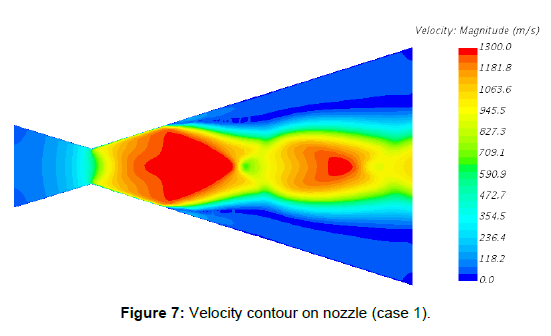
Figure 7: Velocity contour on nozzle (case 1).
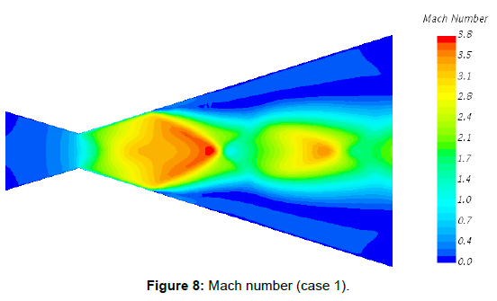
Figure 8: Mach number (case 1).
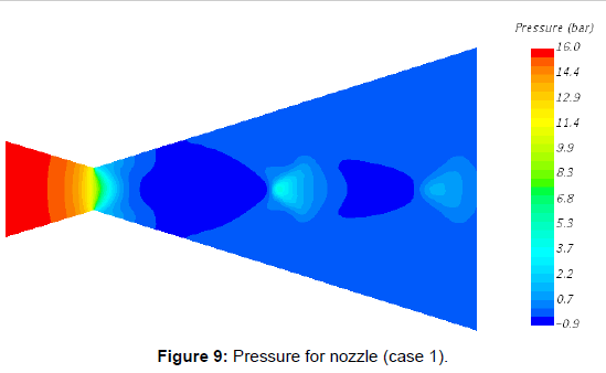
Figure 9: Pressure for nozzle (case 1).
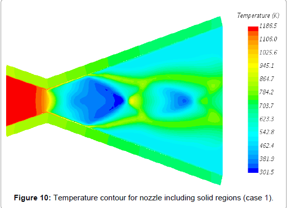
Figure 10: Temperature contour for nozzle including solid regions (case 1).
For case 2, temperature boundary condition has been changed and performed simulation. Similarly, as per case examined Nozzle temperature profile on solid wall. Assisted thermal loading on surrounding structures with Iridium coating [16-18]. Here operating temperature is 2273 K hence generating thermal loads are very high. Due to Iridium coating present in the structure, will withstand the more thermal loading and prevent from the damage during the operation Figures 11-19 [19-24].
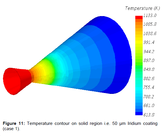
Figure 11: Temperature contour on solid region i.e. 50 μm Iridium coating (case 1).
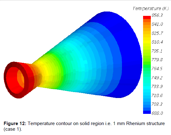
Figure 12: Temperature contour on solid region i.e. 1 mm Rhenium structure (case 1).
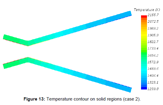
Figure 13: Temperature contour on solid regions (case 2).
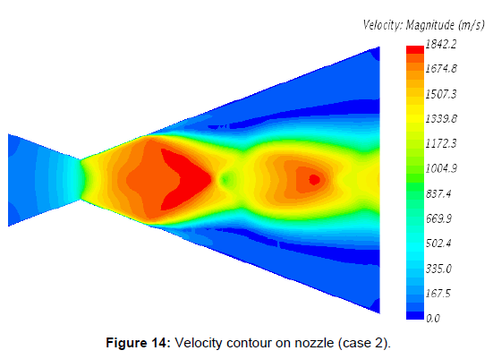
Figure 14: Velocity contour on nozzle (case 2).
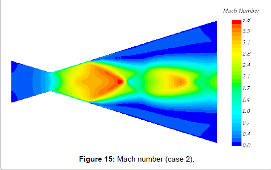
Figure 15: Mach number (case 2).
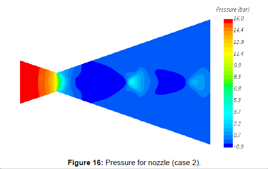
Figure 16: Pressure for nozzle (case 2).
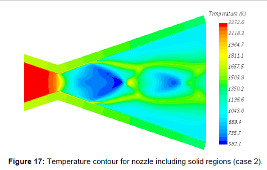
Figure 17: Temperature contour for nozzle including solid regions (case 2).
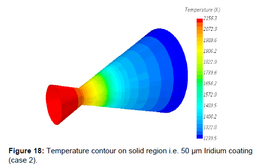
Figure 18: Temperature contour on solid region i.e. 50 μm Iridium coating (case 2).
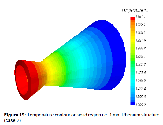
Figure 19: Temperature contour on solid region i.e. 1 mm Rhenium structure (case 2).
From the CFD (FSI) simulation, we have following conclusions:
1. Coupled fluid structure interaction analysis has been carried out on convergent-divergent nozzles of different operating condition.
2. It is observed that, from the both cases velocity increases when pressure values deceases in the convergent-divergent nozzle. Velocity values are suddenly expanded after throat section.
3. Pressure dramatically changing from inlet to the outlet. Higher pressure value notes at the inlet whereas lower value at outlet from the both cases, which is realistic.
4. The present convergent-divergent nozzles size is small and it is simulated or tested for the Mach number 3.8.
5. Iridium coating reduce the thermal loading on surrounding structures and capable of prevent from the damage hence Iridium coating can be used for high-temperature application.
These thermal loads can be used for FEA analysis and assist the deformation due to high thermal loading. Further simulation shall be perform with and without Iridium coating for higher Mach number.
Citation: Keralamatti SS, Pradhani N (2019) Fluid Structure Interaction Based Investigation on Convergent-Divergent Nozzle and Study of Coating Material. J Aeronaut Aerospace Eng, 8: 216; doi: 10.35248/2168-9792.19.8.216
Received: 04-Jan-2019 Accepted: 18-Feb-2019 Published: 26-Feb-2019 , DOI: 10.35248/2168-9792.19.8.216
Copyright: © 2019 Keralamatti SS, et al. This is an open access article distributed under the term of the Creative Commons Attribution License, which permits unrestricted use, distribution, and reproduction in any medium, provided the original work is properly cited.