Journal of Aeronautics & Aerospace Engineering
Open Access
ISSN: 2168-9792
+44-77-2385-9429
ISSN: 2168-9792
+44-77-2385-9429
Mini Review - (2018) Volume 7, Issue 2
Axiomatic design is used as a design methodology for large or complex system design. The first theorem for axiomatic system design describes conditions for equivalence of FRs. The second theorem describes a method of using only leaf levels to represent the hierarchy of the system. A case study of the design of a MALE UAV system is presented. The MALE UAV system architecture is decomposed from top level requirements using the principles of axiomatic design. Also, this work focuses on system interface using N2 diagram which has been first introduced by NASA and also defines the inputs and outputs of each subsystem.
Keywords: MALE UAV; Axiomatic design; N2 diagram; Hierarchy; Interfaces
“Large” system may not be physically large but contains a large number of functional requirements. Therefore, the engineering difficulty in designing systems increased due to the increasing in the number of necessary functions the system must satisfy. As there tends to be interactions between the various elements, a huge number of elements results in a huge number of interactions [1].
With a large number of elements, it is impossible for engineers to predict and track each interaction. Therefore, large systems often have problems during development, due to the large amount of unknown information. The lack of knowledge about interactions leads to poorly designed systems. Since faults are unknown until late in the design process, when resources have been committed, even more expense is incurred in an attempt to make the already designed systems work [2].
The axiomatic design(AD) for the system design is used to manage and track interactions between elements of the system and to fulfil the functions of the design. By doing this, the system will satisfy the required needs. The structure of the axiomatic design method provides the objectivity in organizing design information that is required by large systems. AD becomes an important tool and design methodology in Manufacturing Systems. Many scientists over the world use this methodology for designing systems [3].
The axiomatic design process is focused on the satisfaction of functional requirements (FRs). The minimum set of independent requirements that characterize the design goals are defined by FRs. The system must be developed using design parameters (DPs) that must fulfil the FRs [4]. The designer imagines a physical personification containing a DP that may be adjusted to satisfy the FR. Personifications and DPs are chosen for the design according to the two design axioms:
Axiom 1 (Independence Axiom): Maintain the independence of the functional requirements.
Axiom 2 (Information Axiom): Minimize the information content of the design.
The design matrix relates the FR vector to the DP vector. The design matrix is governed in the following design equation 1:
 (1)
(1)
Where A11 denotes the effect of DP1 on FR1, A21 denotes the effect of DP1 on FR2, etc. When the design equations represent conceptual levels of the design, it is common for the elements of the matrix, Aijto be represented with an ‘X’ if there is an effect, and an ‘O’ if there is no effect. The design matrix must be diagonal or triangular to satisfy the Independence Axiom.
The triangular matrix in Equation 1 represents a decoupled design. For correct developing of such a design, the value of the DP1 must be set before setting the value of DP2.
A diagonal matrix represents an uncoupled design, and the DPs can be set in any order. Axiomatic design begins with general requirements of the system and decomposes them into sub-requirements. Decomposition is used to specify a set of elements that will result in the parent. As the system is decomposed, it is necessary to specify a set of FRs, move to the physical domain by the conception of a design solution and specification of DPs, and then proceed back to the functional domain as required. This process of moving back and forth between the functional and physical domains, and continuing from a general to a detailed description, is called zigzagging as shown in Figure 1. Zigzagging is repeated until it is likely to create the system from the information contained in the system architecture.
During the decomposition process, the system architecture is created according to the preferences of the system designer. The system designer’s preferences determine how FR/DP pairs will be decomposed into sub-systems. The high levels of the design represent conceptual design information that must be enhanced. When sufficient information is contained in a particular FR/DP relationship, the branch of the decomposition is considered finished, and termed a leaf. The system architecture consists of a number of branches, diverging at various levels, and always ending in leaf levels.
System decomposition creates a set of subsystems and the interfaces between them. Designer of each subsystem is usually assigned to his subsystem. But the subsystem interfaces need special attention since each subsystem designer may assume that the other party is responsible for the interface, or each party makes its own assumptions about the interface requirements.
In both cases, the project runs the risk of future interface incompatibility, since the subsystems mature their concepts (and their interfaces) independently. The solution is to explicitly identify who is responsible of every interface.
The N-squared (N2) diagram is used to develop system or subsystem interfaces. The system components or functions are placed on the diagonal and the rest of the squares in the N × N matrix represent the interface inputs and outputs. When there is no interface between the respective components or functions, the squares appear blank. Data flows clockwise between entities (i.e., the symbol F3 → F4, in Figure 2, indicates data flowing from function F3 to function F4; the symbol F4 → F3 indicates the feedback). The N2 diagram can be taken down into successively lower levels to the component functional levels. Besides defining the interfaces, the N2 diagram also locates areas where conflicts could arise in interfaces, and highlights input and output dependency requirements and assumptions [5].
N2 diagram rules:
• Items or functions are on the diagonal.
• Items or functions have inputs and outputs.
• Item or function outputs are contained in rows; inputs are contained in columns.
• If there is bi-directional information flow between functions - this is a feedback loop.
• Consider combining functions where there is a lot of ‘coupling’ (including feedback loops) within a subsystem. This may simplify the subsystem designs and their interfaces.
The case study is performed considering Medium Altitude Long Endurance Unmanned Aerial Vehicles (MALE UAV).
First branch level of hierarchy provides the following FRs and its DPs
FR 1: Carries the payloads and supports their functions, DP 1: Air vehicle.
FR 2: Perform controlling, communication, commanding of the air vehicle, DP 2: Ground segment.
FR 3: Perform reconnaissance and combat, DP 3: Payloads.
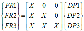
The interaction of first branch level FRs and DPs is represented in equation 2:
 (2)
(2)
Since the matrix for the decomposition of the first branch level requirements is decoupled, it is necessary to completely decompose FR/ DP1 before FR/DP2 and 3. Constraints that govern the mapping from functional requirements to design parameters are shown in Table 1.
| Constraints | FR/DP | ||
|---|---|---|---|
| 1 | 2 | 3 | |
| Volume | X | -- | X |
| Mass | X | -- | X |
| Simple design | X | X | -- |
| Logistic and transportability | X | X | -- |
| Very low emissions/exhaust/noise | X | -- | -- |
| Easy manufacturing | X | -- | -- |
| Strong structure | X | -- | -- |
Table 1: Constraints.
FR/DP1-Carries the payloads and supports their functions/ Air vehicle
At this level of the design, a utility FR is included to support Air Vehicle operations. This enables the designer to specify and include all sub-systems that are necessary to enable the primary systems. Also, a requirement to allow user control is introduced at this level. The specific requirements are listed as follows.
FR 1.1: Structure an aerodynamic and strong Air Vehicle, DP 1.1: Airframe.
FR 1.2: Generate thrust, DP 1.2: Propulsion.
FR 1.3: Non-avionics service subsystems, DP 1.3: Vehicle Subsystems.
FR 1.4: Avionics service subsystems, DP 1.4: Avionics.
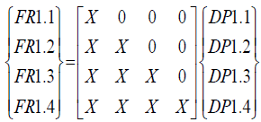
The design equation associated is:
 (3)
(3)
Since the design matrix at this level is decoupled, it is to be continued to follow the FR/DP1.1, until completion. Completing the decomposition of the FR/DP1.1 provides information that may be necessary for completion of other branches.
The decomposition of FR/DP1.1 - Structure an aerodynamic and strong Air vehicle/ Airframe
FR 1.1.1: Generate Longitudinal and directional stability, DP 1.1.1: Tail.
FR 1.1.2: Accommodate payload and subsystems, DP 1.1.2: Fuselage.
FR 1.1.3: Generate lift, DP 1.1.3: Wing.
FR 1.1.4: House an engine, DP 1.1.4: Nacelle.
The design equation associated is:
 (4)
(4)
The decomposition of FR/DP1.1.1 - Longitudinal and directional stability/Tail
FR 1.1.1.1: Generate longitudinal stability, DP 1.1.1: Horizontal tail
FR 1.1.1.2: Generate directional stability, DP 1.1.2: Vertical tail
The design equation associated is:
 (5)
(5)
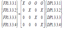
The decomposition of FR/DP1.3 - Non-avionics service subsystems/ vehicle subsystems
FR 1.3.1: Control the flight path of the air vehicle and providing additional lift, drag and trim effect, DP 1.3.1 Primary and secondary mechanical controls, linkage, and control surface actuators
FR 1.3.2: Perform engine start up on the ground, DP 1.3.2 Auxiliary Power Unit (APU)
FR 1.3.3: Facilitate take-off and landing, DP 1.3.3 Landing Gear
FR 1.3.4: Provide electrical power, DP 1.3.4 Electrical Subsystem
FR 1.3.5: Provide fuel to the engines, DP 1.3.5 Fuel Subsystem
The design equation associated is:
 (6)
(6)
The decomposition of FR/DP1.3.3 - Facilitate take-off and landing/landing gear system
FR 1.3.3.1: Slide the AV on the ground, DP 1.3.3.1 Wheels
FR 1.3.3.2: Deaccerlate and stop the AV, DP 1.3.3.2 Braking
FR 1.3.3.3: Retract and extract the gear, DP 1.3.3.3 Pneumatic actuator
FR 1.3.3.4: Steer the gear, DP 1.3.3.4 Electromechanical actuator
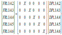
The1 .3d.4e.1sign eq0uat0io0n a0sso0ciated1. 3i.s4:.1
 (7)
(7)
The decomposition of FR/DP1.3.4 - Provide electrical power/ Electrical subsystems
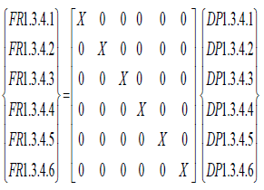
FR 1.3.4.1: Carry electricity power, DP 1.3.4.1 Wiring harnesses
FR 1.3.4.2: Provide electrical power, DP 1.3.4.2 Generators
FR 1.3.4.3: Transform and rectify electrical power, DP 1.3.4.3 Transformer Rectifier Unit
FR 1.3.4.4: Distribute electrical power, DP 1.3.4.4 AC and DC Distribution units
FR 1.3.4.5: Illuminating the AV, DP 1.3.4.5 Exterior Lighting
FR 1.3.4.6: Backup source of electrical power, DP 1.3.4.6 Batteries
The design equation associated is:
 (8)
(8)
The decomposition of FR/DP1.3.5 - Provide fuel to the engines/Fuel Subsystem
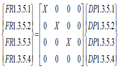
FR1.3.5.1: Carry fuel, DP 1.3.5.1 Fuel Lines
FR1.3.5.2: Fuel Storage, DP 1.3.5.2 Fuel tank
FR1.3.5.3: Pressurize the fuel, DP 1.3.5.3 Pumps
FR1.3.5.4: Measure flow rate and capacity, DP 1.3.5.4 Sensors
The design equation associated is:
 (9)
(9)
The decomposition of FR/DP1.4 - Avionics service subsystems/ Avionics
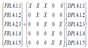
FR 1.4.1: Provide communications and identification, DP 1.4.1 Communication/identification subsystem
FR 1.4.2: Perform the navigational function, DP 1.4.2 Navigation subsystem
FR 1.4.3: Control the flight path, DP 1.4.3 Automatic flight control subsystem
FR 1.4.4: Deliver weapons, DP 1.4.4 Fire control subsystem
FR 1.4.5: Allow a MALE UAV to detect an approaching aircraft, recognize the potential for a collision, and change course to maintain safe separation distances, with or without operator intervention, DP 1.4.5 Traffic Alert and Collision Avoidance System (TCAS)
The decomposition of FR/DP1.4.1-Providing communications and identification/Communication/identification subsystem
FR 1.4.1.1: Modulate the input data stream onto a high frequency carrier prior to transmission, amplify, encrypt, and transmit the signal (telemetry), DP 1.4.1.1 Transmitter 1
FR 1.4.1.2: Receive the signal, demodulate, decrypt the signal, and Identify with external GCS and other AVs (Identification Equipment (IFF) (command), DP 1.4.1.2 Receiver
FR 1.4.1.3: Convert electric power into radio waves, and vice versa, DP 1.4.1.3 Antenna
FR 1.4.1.4: Communicate with satellite, DP 1.4.1.4 SATCOM
FR 1.4.1.5: Modulate the input data stream onto a high frequency carrier prior to transmission, Amplify, Encrypt, and transmit the payload data, DP 1.4.1.5 Transmitter 2
The design equation associated is:
 (10)
(10)
The decomposition of FR/DP1.4.2 - Performing the navigational function/Navigation subsystem
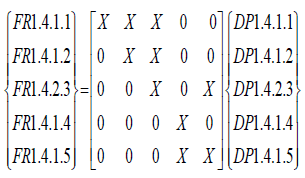
FR 1.4.2.1: Provide a navigation solution, DP 1.4.2.1 The inertial navigation system (INS) (inertial measurement unit and GPS)
FR 1.4.2.2: Measure the altitude, DP 1.4.2.2 Altimeter
The design equation associated is:
 (11)
(11)
The decomposition of FR/DP1.4.3 - Controlling the flight path/Automatic flight control subsystem
FR 1.4.3.1: Process the signal and actuations the actuators, DP 1.4.3.1 Autopilot
FR 1.4.3.2: Measure pressure, DP 1.4.3.2 Pressure Transducers
FR 1.4.3.2: Measure pressure, DP 1.4.3.2 Pressure Transducers
FR 1.4.3.4: Measure acceleration forces, DP 1.4.3.4 Accelerometers
FR 1.4.3.5: Measure the motion of control surfaces, DP 1.4.3.5 Motion Sensors
The design equation associated is:
 (12)
(12)
The decomposition of FR/DP1.4.4 - Delivering weapons/Fire control subsystem
FR 1.4.4.1: Control the firing process, DP 1.4.4.1 Bombing computer
FR 1.4.4.2: Secure bombs, DP 1.4.4.2 Safety devices
The design equation associated is:
 (13)
(13)
The decomposition of FR/DP1.4.5 - Allowing a MALE UAV to detect an approaching aircraft, recognize the potential for a collision, and change course to maintain safe separation distances, with or without operator intervention /Traffic Alert and Collision Avoidance System (TCAS)
Decomposition of FR/ DP2 - Command, Control, and Communications the system/Ground segment
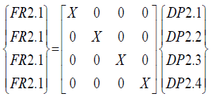
FR 2.1: Communicate with the MALE UAV, DP 2.1 Ground Control Systems
FR 2.2: Send commands and receive telemetry and payload data, DP 2.2 Command and control subsystem
FR 2.3: Land of AV, DP 2.3 Automatic Landing and Recovery Equipment
FR 2.4: Transport AV, crew, maintenance equipment, and direct maintenance personnel, DP 2.4 Transport vehicles
The design equation associated is:

Decomposition of FR/ DP2.1 - Command, control, and communications the system/Ground control segment
FR 2.1.1: Modulate the input data stream onto a high frequency carrier prior to transmission, amplify, encrypt, and transmit the signal (commands), DP 2.1.1 Transmitter
FR 2.1.2: Receive the signal, demodulate, and decrypt the signal (telemetry), DP 2.1.2 Receiver 1
FR 2.1.3: Convert electric power into radio waves, and vice versa, DP 2.1.3 Antenna
FR 2.1.4: Receive the signal, demodulate, and decrypt the signal (payload data), DP 2.1.4 Receiver 2
The design equation associated is:
 (15)
(15)
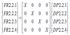
Decomposition of FR/ DP2.2 - Send commands and receive telemetry and payload data/Command and control subsystem
FR 2.2.1: Control and AV status readout, DP 2.2.1 AV Workstation
FR 2.2.2: Control and payload data display, DP 2.2.2 Payload Workstation
FR 2.2.3: Plan mission, DP 2.2.3 Plane mission Workstation
FR 2.2.4: Acquiring weather data, DP 2.2.4 Weather Workstation
The design equation associated is:
 (16)
(16)
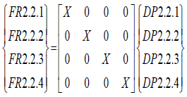
Decomposition of FR/ DP3 - Reconnaissance and combat / Payloads
FR 3.1: Reconnaissance, DP 3.1 Infrared and TV gamble
FR 3.2: Measure distance of targets, DP 3.2 Laser Rangefinder
FR 3.3: Combat, DP 3.3 Bomb
The design equation associated is:
 (17)
(17)
At this point, the system architecture has been completed in sufficient detail to allow the detailed design of the MALE UAV as shown in Table 2 and the leaf components are listed in Table 3.
| Functional Requirements(FRs) | Design Parameters(DPs) |
|---|---|
| Having a system performs reconnaissance, destroys targets, and works in danger areas. | MALE UAV system |
| 1 c carries the payloads and supports their functions | 1 Air vehicle |
| 1.1 Structure an aero-dynamic and strong air vehicle | 1.1 Air frame |
| 1.1.1 Generate longitudinal and directional stability | 1.1.1 Tail |
| 1.1.1.1 Generate longitudinal stability | 1.1.1.1 Horizontal tail |
| 1.1.1.2 Generate directional stability | 1.1.1.2 Vertical tail |
| 1.1.2 Accommodate payload and subsystems | 1.1.2 Fuselage |
| 1.1.3 Generate lift | 1.1.3 Wing |
| 1.1.4 House an engine | 1.1.4 Nacelle |
| 1.2 Generate thrust | 1.2 Propulsion |
| 1.3 Non-avionics service subsystems | 1.3 Vehicle subsystems |
| 1.3.1 Control the flight path of the air vehicle and providing additional lift, drag and trim effect. | 1.3.1 Primary and secondary mechanical controls, linkage, and control surface actuators |
| 1.3.2 Perform engine start up on the ground | 1.3.2 Auxiliary Power Unit (APU) |
| 1.3.3 Facilitate take-off and landing | 1.3.3 Landing gear |
| 1.3.3.1 Slide the AV on the ground | 1.3.3.1 Wheels |
| 1.3.3.2 Deaccerlate and stop the AV | 1.3.3.2 Braking |
| 1.3.3.3 Retract and extract the gear | 1.3.3.3 Pneumatic actuator |
| 1.3.3.4 Steer the gear | 1.3.3.4 Electromechanical actuator |
| 1.3.4 Provide electrical power | 1.3.4 Electrical subsystem |
| 1.3.4.1 Carry electricity power | 1.3.4.1 Wiring harnesses |
| 1.3.4.2 Generate electrical power | 1.3.4.2 Generator |
| 1.3.4.3 Transform and rectify electrical power | 1.3.4.3 Transformer Rectifier Unit |
| 1.3.4.4 Distribute electrical power | 1.3.4.4 AC And DC distribution units |
| 1.3.4.5 Illuminating the AV | 1.3.4.5 Exterior lighting |
| 1.3.4.6 Backup source of electrical power | 1.3.4.6 Batteries |
| 1.3.5 Provide fuel to the engines | 1.3.5 Fuel subsystem |
| 1.3.5.1 Carry fuel | 1.3.5.1 Fuel lines |
| 1.3.5.2 Fuel Storage | 1.3.5.2 Fuel tank |
| 1.3.5.3 Pressurize the fuel | 1.3.5.3 Pumps |
| 1.3.5.4 Measure flow rate and capacity | 1.3.5.4 Sensors |
| 1.4 Avionics service subsystems | 1.4 Avionics |
| 1.4.1 Providing communications and identification | 1.4.1 Communication/identification subsystem |
| 1.4.1.1 Modulate the input data stream onto a high frequency carrier prior to transmission, amplify, encrypt, and transmit the signal (telemetry) | 1.4.1.1 Transmitter 1 |
| 1.4.1.2 Receive the signal, demodulate, decrypt the signal, and Identify with external GCS and other AVs (Identification Equipment (IFF) (command) | 1.4.1.2 Receiver |
| 1.4.1.3 Convert electric power into radio waves, and vice versa. | 1.4.1.3 Antenna |
| 1.4.1.4 Communicate with satellite | 1.4.1.4 SATCOM |
| 1.4.1.5 Modulate the input data stream onto a high frequency carrier prior to transmission, amplify, encrypt, and transmit the payload data | 1.4.1.5 Transmitter 2 |
| 1.4.2 Performing the navigational function | 1.4.2 Navigation subsystem |
| 1.4.2.1 Provide a navigation solution | 1.4.2.1 The inertial navigation system (INS) (inertial measurement unit and GPS) |
| 1.4.2.2 Measure the altitude | 1.4.2.2 Altimeter |
| 1.4.3 Controlling the flight path | 1.4.3 Automatic flight control subsystem |
| 1.4.3.1 Process the signal and actuations the actuators | 1.4.3.1 Autopilot |
| 1.4.3.2 Measure pressure | 1.4.3.2 Pressure transducers |
| 1.4.3.3 Indicate direction | 1.4.3.3 Rate Gyros |
| 1.4.3.4 Measure acceleration forces | 1.4.3.4 Accelerometers |
| 1.4.3.5 Measure the motion of control surfaces | 1.4.3.5 Motion sensors |
| 1.4.4 Delivering weapons | 1.4.4 Fire control subsystem |
| 1.4.4.1 Controlling the firing process | 1.4.4.1 Bombing computer |
| 1.4.4.2 Securing bombs | 1.4.4.2 Safety devices |
| 1.4.5 Allowing a MALE UAV to detect an approaching aircraft, recognize the potential for a collision, and change course to maintain safe separation distances, with or without operator intervention. | 1.4.6 Traffic Alert and Collision Avoidance System (TCAS) |
| 2 Command, control, and communicate with the system | 2 Ground segment |
| 2.1 Communicate with MALE UAV | 2.1 Ground control systems |
| 2.1.1 Modulate the input data stream onto a high frequency carrier prior to transmission, amplify, encrypt, and transmit the signal (commands) | 2.1.1 Transmitter |
| 2.1.2 Receive the signal, demodulate, and decrypt the signal (telemetry) | 2.1.2 Receiver 1 |
| 2.1.3 Convert electric power into radio waves, and vice versa. | 2.1.3 Antenna |
| 2.1.4 Receive the signal, demodulate, and decrypt the signal (payload data) | 2.1.4 Receiver 2 |
| 2.2 Send commands and receive telemetry | 2.2 Command and control subsystem |
| 2.2.1 Control and AV status readout | 2.2.1 AV Workstation |
| 2.2.2 Control and payload data display | 2.2.2 Payload workstation |
| 2.2.3 Plane mission | 2.2.3 Plane mission workstation |
| 2.2.4 Acquiring weather data | 2.2.4 Weather workstation |
| 2.3 Land of AV | 2.3 Automatic landing and recovery equipment |
| 2.4 Transport AV, crew, maintenance equipment, and direct maintenance personnel | 2.4 Transport vehicles |
| 3 Reconnaissance and combat | 3 Payloads |
| 3.1 Reconnaissance | 3.1 Infrared, TV |
| 3.2 Measure distance of targets | 3.2 Laser rangefinder |
| 3.3 Combat | 3.3 Bomb |
Table 2: General decomposition of FR/ DP of MALE UAV.
| No. | Leaf component |
|---|---|
| 1 | 1.1.1.1 Horizontal tail |
| 2 | 1.1.1.2 Vertical tail |
| 3 | 1.1.2 Fuselage |
| 4 | 1.1.3 Wing |
| 5 | 1.1.4 Nacelle |
| 6 | 1.2 Propulsion |
| 7 | 1.3.1 Primary and secondary mechanical controls, linkage, and control surface actuators |
| 8 | 1.3.2 Auxiliary Power Unit (APU) |
| 9 | 1.3.3.1 Wheels |
| 10 | 1.3.3.2 Braking |
| 11 | 1.3.3.3 Pneumatic actuator |
| 12 | 1.3.3.4 Electromechanical actuator |
| 13 | 1.3.4.1 Wiring harnesses |
| 14 | 1.3.4.2 Generator |
| 15 | 1.3.4.3 Transformer Rectifier Unit |
| 16 | 1.3.4.4 AC And DC Distribution units |
| 17 | 1.3.4.5 Exterior lighting |
| 18 | 1.3.4.6 Batteries |
| 19 | 1.3.5.1 Fuel lines |
| 20 | 1.3.5.2 Fuel tank |
| 21 | 1.3.5.3 Pumps |
| 22 | 1.3.5.4 Sensors |
| 23 | 1.4.1.1 Transmitter 1 |
| 24 | 1.4.1.2 Receiver |
| 25 | 1.4.1.3 Antenna |
| 26 | 1.4.1.4 SATCOM |
| 27 | 1.4.1.5 Transmitter 2 |
| 28 | 1.4.2.1 The inertial navigation system (INS) (inertial measurement unit and GPS) |
| 29 | 1.4.2.2 Altimeter |
| 30 | 1.4.3.1 Autopilot |
| 31 | 1.4.3.2 Pressure transducers |
| 32 | 1.4.3.3 Rate gyros |
| 33 | 1.4.3.4 Accelerometers |
| 34 | 1.4.3.5 Motion sensors |
| 35 | 1.4.4 Fire control subsystem |
| 36 | 1.4.4.1 Bombing computer |
| 37 | 1.4.4.2 Safety devices |
| 38 | 1.4.5 Traffic Alert and Collision Avoidance System (TCAS) |
| 39 | 2 Ground segment |
| 40 | 2.1 Ground Control Systems |
| 41 | 2.1.1 Transmitter |
| 42 | 2..1.2 Receiver 1 |
| 43 | 2.1.3 Antenna |
| 44 | 2.1.4 Receiver 2 |
| 45 | 2.2 Command and control subsystem |
| 46 | 2.2.1 AV workstation |
| 47 | 2.2.2 Payload workstation |
| 48 | 2.2.3 Plane mission workstation |
| 49 | 2.2.4 Weather workstation |
| 50 | 2.3 Automatic landing and recovery equipment |
| 51 | 2.4 Transport vehicles |
| 52 | 3 Payloads |
| 53 | 3.1 Infrared, TV |
| 54 | 3.2 Laser rangefinder |
| 55 | Bomb |
Table 3: Leaf components of MALE UAV.
 (18)
(18)
The MALE UAV system as a whole comprises several main subsystems and components, each of which plays a vital role in the operation of the vehicle. The navigation subsystem gathers information regarding the vehicle's position, and motion. Traffic Alert and Collision Avoidance Subsystem (TCAS)is responsible for providing collision avoidance capability. Primary and secondary mechanical controls, linkage, and control surface actuators, control the flight path of the air vehicle and providing additional lift, drag and trim effect. Automatic flight control subsystem is responsible for the physical control of the MALE UAV in flight; it manoeuvres the vehicle in response to signals either from the estimation system (automatic control, such as for collision avoidance) or the communication subsystem (manual control commands from the ground station). Communication/identification subsystem serves as the interface between the command and control subsystem and ground control subsystems and the other subsystems. It receives commands by wireless radio signal from the ground control subsystems or from satellite and sends images and other data from the vehicle to the ground. These images are obtained by the Infrared, TV imaging subsystem. Fire control subsystem controls the realizing of bombs. Landing gear facilitates take-off, landing, and taxing. The propulsion subsystem generates and regulates the thrust required to keep the MALE UAV aloft and perform the mission, which is supplied with fuel from fuel subsystem. Electrical subsystem provides all the onboard components with electrical power, at the required voltage and current levels.
N2 diagram is a graphical method that representing the interfaces between subsystems. An N2 diagram is an N by N matrix (where N is the number of subsystems which make up the system as a whole), which details the interfaces which flow from subsystem to subsystem. The N2 diagram for the MALE UAV is shown in Figure 3.
Interfaces flow in a clockwise direction, so the interfaces between main subsystems are:
• Electrical subsystem provides all the on-board components with “electrical power”, at the required voltage and current levels.
• “UAV position and speed” are sent from automatic flight control subsystem to a traffic alert and collision avoidance subsystem (TCAS), while “traffic status and alerts” are sent to communication/identification subsystem and then to ground control subsystems.
• The navigation subsystem provides automatic flight control subsystem with “UAV position and speed”.
• “Control flight surface” are sent from automatic flight control subsystem to primary and secondary mechanical controls, linkage, and control surface actuators.
• "Camera commands" are sent from the communication/ identification subsystem or automatic flight control subsystem to the Infrared, TV imaging subsystem, while "image data" is sent from the Infrared, TV imaging subsystem to the communication/identification subsystem.
• “Control/camera/fire commands” are sent from ground control subsystems to communication/identification subsystem, while “traffic status and alerts, telemetry data, and imaging data” are sent to communication/identification subsystem from traffic alert and collision avoidance subsystem (TCAS), automatic flight control subsystem, and Infrared, TV imaging subsystem respectively.
• "Throttle commands" are sent from the automatic flight control subsystem to the propulsion subsystem, while “engine telemetry data” is sent from the propulsion subsystem to the automatic flight control subsystem.
• “Braking commands" are sent from automatic flight control subsystem to land gear subsystem.
• “Fire commands" are sent from the communication/ identification subsystem or automatic flight control subsystem to the fire control subsystem.
• “Imaging and telemetry data” are sent from ground control subsystems to command and control subsystem, while “control commands” are sent to ground control subsystems from command and control subsystem.
In AD, the problem description and the solution are developed in a gradual evolution starting from an analysis of needs, then generate possible solutions and with top-down and mapping between problem (FR) and solution (DP). The objectives of this paper are to apply the AD methodology to support the design stage of MALE UAV, where it is broken down up to the fourth-level and a list of leaf components is developed. Also, to developed N2diagram is a graphical method that represents the interfaces between MALE UAV subsystems and defines the inputs and outputs of each subsystem.