International Journal of Advancements in Technology
Open Access
ISSN: 0976-4860
+44 1478 350008
ISSN: 0976-4860
+44 1478 350008
Research Article - (2018) Volume 9, Issue 4
The theoretical model for calculation of heat transfer is developed at turbulent flow in channels in conditions of heat transfer enhancement distinguished from known models by higher accuracy, the absence of additional assumptions, and an account of the greater number of parameters rendering influence to processes of heat transfer. The computation data on nonisothermal heat transfer largely appropriate to experimental data are obtained. For the first time, a theoretical model for calculation of nonisothermal heat transfer and hydraulic resistance is developed at turbulent flow in tubes in conditions of heat transfer enhancement for various kinds of heat-carriers (gas, dropping liquid) with variable thermophysical properties changed by a monotone image. The computation data for a broad band of turbulizers parameters and regime parameters are obtained. For the first time, a theoretical model for calculation of no isothermal heat transfer and hydraulic resistance is developed at the turbulent flow of Jet Fuel Of Supercritical Pressure (JFSCP) in tubes in the condition of heat transfer enhancement on the base of the four-layer scheme of turbulent flow.
Keywords: Hydraulic resistance; Turbulizers; Heat transfer
à Constant:
cp Heat capacity at constant pressure kJ/kg⋅К
 The average heat capacity of the heat-carrier in an interval of temperatures from
The internal diameter of a tube ( R0 = D / 2 ), m
FΣ Full area of a rough surface, m2
Fsm Area of a surface of a smooth tube, m2
h The height of a turbulizer, m
hw and fh Enthalpy of the heat-carrier at the temperature of the wall and its mean-mass enthalpy, kJ/kg

 Constants dependent on the nature of gas and an interval of temperatures
 Nusselt number, designed on the formula (19)
NuT The nusselt number for conditions of JGSCP flow in a smooth tube

 Pressure, Pа
Pr Prandtl number: 
Prt Turbulent Prandtl number: 
qwn Heat flux referred to a surface FΣ , W/m2
R dimensionless radius: 
t The step between turbulizers, m
T Temperature, К
Tm Pseudo-critical temperature, К
Tw and Tf Wall temperature and mean-mass temperature of flow accordingly, К
p Velocities along an axis of a tube and radius, m/s
β Constant (for a smooth pipe β = 0.023 )
ετ Turbulent viscosity, m2/s
εq Turbulent thermal diffusivity, m2/s

 The dimensionless thickness of a viscous sublayer, which under the experimental data for boundary layers of a different structure:
  ≈ 5
≈ 5
θw Dimensionless wall temperature; 
λ Thermal conductivity, W/m⋅К
μw Dynamic viscosity, Pа⋅s
μw and μf Value of dynamic viscosity of a flow at the temperature of the wall and mean-mass temperature of a flow accordingly, Pa⋅s ;
ν Kinematic viscosity: ν = μ / ρ , m2/s
νT Turbulent viscosity appropriate to an intermediate profile of velocity: 
ξ The coefficient of friction
Π0 Value of certain thermal parameter at current temperature Π Value of certain thermal parameter at some fixed temperature T0
ρ, cp, λ, μ Value of appropriate physical properties at the current temperature T Density, kg/m3
 Value of appropriate physical properties at wall temperature Tw
τ and q Total (molecular and turbulent) tangential pressure and radial heat flux, N/m2 и W/m2
 The pressure of friction referred to a surface FΣ, N/m2 subscripts
DB Dittus-Boelter
f Mean-mass
int Intermediate layer
m Pseudo-critical
r Radial
sm Smooth
t, T Turbulent
vs Viscous sublauer
vcl Vortical core layer
w Wall
x Axial
The problem of reducing the mass and size heat exchangers is urgent. Enhancement of convective heat transfer processes is a promising means for solving this problem. At present, different methods of heat transfer enhancement in channels have been proposed and studied [1,2].
Heat transfer in tubes at the flow of heat-carries with constant thermal properties in conditions of heat transfer enhancement is simulated on the basis of a four-layer scheme of turbulent flow. From numerous results of the previous researches [3,4]. it is known, that at the definite depth of cavities roughness (smaller than 20 thicknesses of a viscous sublayer), i.e. at the regime of a developed roughness, the fixed vertical flow with regular vortexes is observed. The number and arrangement of these vortexes depend on a relative pitch between protrusions. The roughness is considered as a system of protrusions and cavities; in last the steady regular vortex generations are formed (Figure 1).
A streamlining of the closely located cavities the role of stagnation points is insignificant (for example, there are no brightly expressed stagnation points), therefore the modified Reynolds analogy is approximately correct.
The analysis [5,6] shows, that in rough pipes the thermal resistance of turbulent core makes of the order (10-13)% from common thermal resistance, therefore total error at the calculation of heat transfer will not exceed 5%. Therefore, the violation of the Reynolds analogy will be in this case insignificantly reflected in results of heat transfer calculation. The good coincidence of results of calculations with experimental data testifies also to it [5,6]. In a rough tube, the boundary layer contains four sublayers: a viscous sublayer, intermediate area, vortical core in a cavity, a turbulent core with the stabilized velocity profile.
For each sublayer, the temperature drops are determined, on which it is rather easy to define dimensionless heat transfer coefficient -Nusselt number. Within the framework of the given research the above-stated four-layer scheme of turbulent flow was applied without additional assumptions connected to an error of approximations, and in view of all members in final computational equations, that is expedient distinguishes the given research from all more early.
Heat transfer and hydraulic resistance for nonisothermal flow in tubes in conditions of heat transfer enhancement are simulated on the basis of the four-layer scheme for turbulent flow, which was successfully applied within the framework of the given research at the calculation of isothermal heat transfer enhancement at turbulent flow. The legitimacy of modelling of nonisothermal heat transfer and resistance at turbulent flow in tubes in conditions of heat transfer enhancement with this scheme is stipulated by that the assumptions used at a conclusion of equations, circumscribing nonisothermal heat transfer in conditions of turbulent flows in smooth tubes (uniformity and isotropy of the heat-carrier, the energy of deformation is small on a comparison with change of internal energy, the diffusion is absent, the mass forces are small on a comparison with forces of inertia and of internal friction), in a sufficient measure are correct and for conditions of heat transfer enhancement. By the major factor stipulating the legitimacy of the given approach based on the use of properties of generalized coordinates [7-9].
Heat transfer at the flow of Jet Fuel Of Supercritical Pressure (JFSCP) in conditions of heat transfer enhancement takes place under following conditions: pressure is higher critical and temperatures close to pseudo-critical (for jet fuel Tm = 653 K at p = 2.5 ÌÐà ), when a maximum of heat capacity at constant pressure has a place.
The specific feature of single-phase heat-carriers, in particular of hydrocarbon fuels in pseudocritical areas is, that their physical properties change very much hardly and nonmonotonically in dependence on temperature and essentially depend on pressure. The major distinctive feature or dependence thermophysical properties of jet fuels from temperature consists that in pseudocritical region change of dynamic viscosity is less strong, than for other heat-carriers.
The interest to the given problem is called by use of hydrocarbon fuels as a coolant of heat-stressed components of vehicle engines. The possibility of these fuels used for cooling can be essentially improved as a result of endothermal decomposition reactions. Also, the presence of supercritical cooling parameters allows high values of heat transfer coefficients to be obtained [1].
The theoretical results concerning the influence of the temperature factor in conditions artificial flow turbulization allow developing a technique of calculation of nonisothermal heat transfer and resistance in conditions of heat transfer enhancement at the flow of heat-carriers with supercritical parameters.
Researches of heat transfer and resistance in conditions of a smooth tube at the flow of heat-carriers of supercritical parameters are devoted to many experimental and theoretical works sufficiently explaining laws of heat transfer for these conditions. There are experimental researches of heat transfer and resistance in conditions of heat transfer enhancement at the flow of hydrocarbon fuels of supercritical parameters [10-13], permitting an empirical image to determine areas and methods of heat transfer enhancement. It is proved, that higher, than a flow of other kinds of heat-carriers, the effects of heat transfer enhancement can be reached at hydrocarbon fuels flow of supercritical parameters [1]. The review of both experimental and theoretical works are adduced in the monograph [14].
The modelling of heat transfer at flow hydrocarbon fuels (JFSCP) is made on the base of four-layer scheme for turbulent flow at variable properties of heat-carrier, characteristic for JF in pseudocritical region, with boundary conditions of constant heat flux density on the wall, as well as for heat-carriers, which properties are changed by a monotone image.
For a boundary layer in a rough tube, we shall consider the fourlayer scheme (Figure 2): I-viscous sublayer; II-intermediate area; IIIvortical core in a cavity; IV-turbulent core with the stabilized velocity profile in the main flow.
Within the framework of the given model, we shall consider, that the height of a roughness h << D .
Within the boundaries of a viscous sublayer, it is possible to count owing to small its thickness, that of friction and heat flux practically correspond to their values on a wall [4,5]. Therefore, the temperature drop in a viscous sublayer will be equal (4):
 (1)
(1)
In [4,5] it is proved, that νT ∝ y3. In dimensionless coordinates:  .
.
Therefore, the temperature drop in a viscous sublayer will be equal:
 (2)
(2)
The integration of equation (2), agrees (5), gives:

 (3)
(3)
The comparison with the computational data adduced in [5], has shown, that for Prandtl numbers Pr = 0.7 ÷ 500 the computational data made pursuant to the laws of the "third" ( νT ∝ y3 ) and "fourth" ( νT ∝ y4 ) degrees, are given approximately the same results.
The equation (3) is approximated as follows (5):
 (4)
(4)
In this work, these were established, that the formula (4) is rather approximate, especially in the field of large Prandtl numbers, where it results in essential divergences with the exact solution. Especially it is necessary to mention, that, strictly speaking, the formula (3) also is to a certain extent approximating, because in the precision analytical solution  , and in the formula (3) this constant is equal 0.303. The similar rounding off also introduces certain inaccuracy in the calculation of isothermal heat transfer enhancement at turbulent flow in channels. In this research the integral (2) was calculated numerically, that has allowed completely to avoid an error of calculations connected to additional assumptions, adopted at approximation.
The temperature drop in an intermediate sublayer is determined as follows:
 (5)
(5)
The integration of expression (5) gives:
 (6)
(6)
In (5) it is proved, that according to researches of a flow structure in an area appropriate to a vortical core, the profiles of velocity are subject to regularities for free jets. Therefore, it is possible to count, that an area from the end of a transient zone up to the tops of roughness the turbulent viscosity saves the constant value. By using the expression for universal velocity profile in a rough tube  , we shall receive expression for turbulent viscosity:
 (7)
(7)
This equation is correct for a broad class of roughness, since constant A describing a kind of a roughness, does not enter in the expression for νT/ν .
For calculation of heat transfer, the value of hydraulic resistance coefficient ξ for rough surfaces or surfaces with turbulizers are entered on the base of experimental data or in a result of calculations using available empirical equations. It is possible to define the minimum value of a limiting coefficient of resistance, i.e. friction coefficient for conditions of a limiting heat transfer enhancement for the account of flow turbulization, with the help of integral method stated in [15].
Therefore, the temperature drop in a vertical core in a cavity will be equal:

 (8)
(8)
For the turbulent core of flow (5):
 (9)
(9)
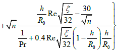
Summarizing temperature drops for each from sublayers and passing to dimensionless to values; we receive expression for Nusselt number:


 (10)
(10)
In equation (10) Nusselt number is referred to as a smooth surface. At large distances between elements of a roughness, the regular vortexes will occupy a small part of the distance between the indicated elements. Therefore a scheme with a vortical core, in this case, will not be correct; the boundary of a vertical core in a cavity will be not the line y = h, but the line
Therefore, when the altitude of a roughness is less than a thickness of intermediate area, i.e. in case  the expression for the Nusselt number will be:


 (11)
(11)
In Figure 3 the results of calculations of the Nusselt number depending on the Reynolds number on an above-stated updated technique are adduced at air flow for tubes with various roughness.

As district from [5,6] this research has not to defect connected to a considerable error of approximation of an integral on the dimensionless thickness of a viscous sublayer. A divergence of this integral value with the precision solution is especial considerably at large Prandtl numbers. The precision solution also allows making the conclusion that the values of integrals (2) and (12) are much more conservative in relation to parameters of heat transfer: to Reynolds and Prandtl numbers and to the constant β than adduced in [5,6]. Also, there was received that smaller divergence of values of the above-mentioned integrals at the replacement of the law "of the third degree" on the law "of the fourth degree" than stated in the same researches [5,6]. The above-mentioned conservatism of integrals (2) and (12) allows making the conclusion that the results concerning dependence of
Nusselt numbers from Prandtl number, adduced in [5,6], are obviously overstated.
1. Modeling of Heat Transfer in Tubes Flow of Heat-Carrier with Variable Properties
Turbulent liquid flow and heat transfer in a round tube are described by a set of equations in the form of boundary layer equations, which for the incompressible heat-carrier with variable physical properties provided that the dissipation of energy is small, has a kind [16-19]:
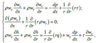 (12)
(12)
Where 
The equations of motion and energy in (12) are recorded in an approximation of a boundary layer. The boundary conditions for the case of tube flow look like:
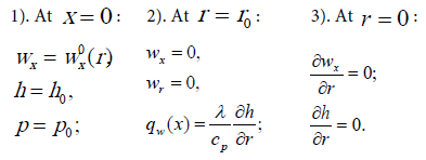
For heat-carrier in round tube with turbulizers there will correct following simplifications [16-19].
1. The quasi-stationarity of the heat-carrier flow and heat transfer far from the inlet are considered
2. The physical properties of the heat-carrier arbitrary depend on temperature
3. It is supposed, that the physical properties of the heat-carrier within the limits of a pulsation of temperature are changed insufficiently, therefore their values in the given point can be accepted by constants and equal to values of physical properties at a mean value of temperature in the given point
4. Change of heat flux density along axis stipulated by heat conductivity and turbulent transfer is small on a comparison with the change along a radius
5. A change viscous and turbulent tangential stress along azimuth and lengths is small on a comparison with change, along with a tube radius
Axial mass velocity component changes a little along an axis of a tube: 
After the account of the above-mentioned assumptions, the equations of motion and energy will be to look as follows:
 (13)
(13)
In conditions of heat transfer enhancement, the assumption about constancy on a cross-section of a tube of derivatives ∂/∂x will be correct.
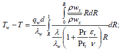
In this work, the heat flux density on a wall is necessary to a constant, therefore, the equations (13) can be reduced to integral equation concerning the Nusselt number and friction resistance coefficient:
 (14)
(14)
 (15)
(15)
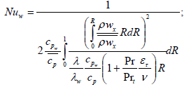 (16)
(16)
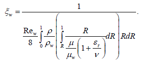 (17)
(17)
In equations (14-17):

For the solution of the equations system (14-17) for conditions of flow in a tube and of heat transfer enhancement, it is necessary to divide a boundary layer into four sublayers. Hereinafter we consider separately each sublayer, using a series of assumptions, characteristic both for nonisothermal and for isothermal flow because the flow has sufficient conservatism in this condition. The conservatism of the above-mentioned characteristics is based on experimental data [1,9]. In this work, it is convincingly proved, that the nonisothermal influence on heat transfer is considerably exhibited at laminar flow, at turbulent flow this influence is reduced, and at flow in conditions of heat transfer enhancement, this influence is even lower.
At modeling of nonisothermal heat transfer and hydraulic resistance at turbulent gas flow in tubes in conditions of heat transfer enhancement, the following additional assumptions are received. The gas is considered ideal. The thermal properties (heat capacity, thermal conductivity, dynamic viscosity) practically do not depend on pressure and are considered only a function of temperature. Being based on numerous works devoted to theoretical researches of nonisothermal heat transfer in smooth pipes [16-19], with a sufficient degree of accuracy there is received:
 (18)
(18)
For example, for air: nλ = 0.789, nμ = 0.150, nc= 0.689.
At modeling of nonisothermal heat transfer enhancement at turbulent gas flow in tubes with the full basis the following assumptions based on experimental materials [1,9], can be adopted: it is possible to neglect by deformation of temperature and velocity profiles and turbulence characteristics in a result of nonisothermal influence. Hereinafter the comparison of nonisothermal heat transfer and resistance with isothermal will be made at Rew = idem.
In Figure 4 the dependence of a relative parameter of heat transfer Nu / Nu0 (θw ) for air at h / R0 0.1; = ξ = 0.3 is shown at the change of value θw = 0.5÷1.8 for various Reynolds numbers obtained on the four-layer scheme of turbulent flow. As it is visible from this fig., the model fully corresponds to the physical fundamentals of the process.
From these theoretical computational results adduced in Figure 4, follows, that nonisothermity in conditions of heat transfer enhancement renders noticeably smaller influence to heat transfer, that in conditions of a smooth tube, that completely corresponds to experimental data (9).
At calculation of nonisothermal heat transfer at JFSCP flow, the following specific assumptions based on experimental data were adopted [20-22]. The mass assumption at the calculation of isothermal profiles of velocities and temperatures in conditions of nonisothermal heat transfer enhancement for JFSCP flow. The justification of the similar approach for conditions consists of experimental fact, that the application of artificial turbulizers allows largely to loosen influence of mass forces to heat transfer process [1], which stipulate origin of regimes of the "worsened" heat transfer for conditions of a smooth channel [1,23].
For JF the specific feature is, that the change of dynamic viscosity happens in a much smaller degree than for other heat-carriers (carbon dioxide, water, helium etc.) because the area of greatest its decrease with the growth of temperature lies in the area of much lower temperatures than temperature m Tm . Therefore, there is one more factor, supporting conservatism of velocities and temperatures profiles in conditions of heat transfer enhancement. The remaining assumptions at the calculation of heat transfer at JFSCP flow remain the same, as well as at calculation of heat transfer for heat-carriers, which physical properties are changed by a monotone image.
For the offered four-layer scheme of turbulent flow with constant heat flux density on the wall the program of calculation of nonisothermal heat transfer enh ancement for JFSCP was developed. Using this program the calculations for the following ranges of flow and geometric parameters of turbulizers were conducted: 

The results of theoretical calculation allow receiving the data for a more broad range of parameters of flow in dependence on the temperature factor on a comparison with the existing data.
Hereinafter we shall not stay on heat transfer in a smooth tube explicit because this problem sufficiently reflected in the appropriate literature, in which many are adduced experimental [20-22], and theoretical [18,19] researches sufficiently explaining laws of heat transfer for these conditions.
The regimes of a heat transfer at supercritical pressure are conditionally subdivided on so-called "normal", "improved" and "worsened"[24].
For suppression of regimes of the worsened heat transfer and a decrease of wall temperature, the application of tubes with annular turbulizers is effective for heat transfer processes enhancement in near wall region. For conditions of JFSCP flow if there is heat transfer enhancement the character of heat transfer hardly will be changed on a comparison with a smooth tube, that allows almost completely to exclude the area of the worsened heat transfer [1,13].
The calculation of JFSCP heat transfer for a smooth tube was conducted under the empirical formulas (19)-(20), offered in (13), obtained by results of experiments immediately for JF for above-stated regimes (for Re104, Pr=2÷5, 0.58 ≤ Tf /Tm ≤ 0.92 ). With accuracy 10% these result correspond them:

 ; (19)
 (20)
(20)
The results of calculation in the form of lines of constant Nusm /NuT values are adduced in Figure 5, from which 3 above-stated areas clearly are visible. On an axis of abscissas the values of wall temperature Tw , on an ordinate axis-value mean-mass temperatures Nusm /NuT are postponed. The numbers designate the boundaries of areas of constant relations Nusm /NuT . The areas of worsened, normal and improved heat transfer place accordingly there, where the Nusm /NuT is less, equally or more than one. Results of heat transfer calculation enhancement for conditions of JFSCP flow conducted on the four-layer scheme of the turbulent boundary layer with constant heat flux on the wall, in the form of lines of constants values Nusm /NuT for an above-stated range of parameters  d/D=0.9; t/D=1.0), is adduced in Figure 6.
The analysis of the computational data shows, those three main areas can be chosen: area of a low enhancement of heat transfer, the area of a normal heat transfer enhancement and area of a high enhancement.
Let's define each from above-stated areas.
Area of normal heat transfer enhancement is the area, in which the level of enhancement for conditions of flow of the heat-carrier of supercritical pressure is close to a level of enhancement for the heatcarrier with constant thermal properties with other things being equal. Area of low enhancement of heat transfer is the area, in which the level of heat transfer enhancement for the heat-carrier of supercritical pressure is lower than a level of enhancement for the heat-carrier with constant thermal properties with other things being equal, and the area of high heat transfer enhancement is the area, in which this level is higher. It is natural, that the main interest represents an area of high enhancement, therefore one from main purposes of theoretical research of heat transfer and resistance at JFSCP flow in conditions of heat transfer enhancement will be the installation of parameters combinations ensuring the realization of above-stated areas. By determining parameters for calculation of heat transfer mean-mass temperature and wall temperature were adopted. It is necessary to mark, that the knowledge of these temperatures allows defining (in case of necessity) all remaining parameters: an enthalpy, heat flux density etc., earlier used for generalization of experimental data, for example, in researches [2,21,22]. Thus, it is possible easily to compare the obtained new data with earlier obtained.
The area of a high heat transfer enhancement is in the following area: mean-mass temperature is equal to pseudo-critical temperature, and the maximum enhancement will take place then, when the wall temperature is more than pseudo-critical temperature; a little smaller enhancement will take place at cooling, when the wall temperature is less than pseudo-critical temperature, however, and in this case area of a high heat transfer enhancement will take place.
The area of normal heat transfer enhancement is in the following area: mean-mass temperature is a little below than pseudo-critical temperature, except for area, when the mean-mass temperature is equal to wall temperature.
The area of a low heat transfer enhancement is in the following area: mean-mass temperature is a little above than pseudo-critical temperature, and also the area when the mean-mass temperature is equal to wall temperature.
It is necessary to remind, that the above-stated area of a high heat transfer enhancement in case of a smooth tube is an area of the worsened heat transfer-therefore, the maximum effect of heat transfer enhancement can be reached just in this area.
The results of theoretical calculation of JFSCP of heat transfer on the four-layer scheme of turbulent boundary layer were compared to calculation results under the empirical formulas (21-22): the computational dependence can be circumscribed by the empirical formulas in a broadband. Both those and other are obtained for various regimes of flow and relative sizes of turbulizers for various combinations of wall temperature and mean-mass flow temperatures.
Analyzing of calculation results of heat transfer enhancement for JFSCP for all ranges of parameters change, it is possible to make the conclusion that they can be circumscribed by a satisfactory image (with an error no more than ± 10%) following empirical formulas [1,13]:

 , (21)
for Re≥104; d/D=0.85÷0.95; t/D=0.75÷1;

 , (22)
For Re≥104; d/D=0.85÷0.95; t/D=1.0÷2.0.
The equations (21-22) were offered for isothermal heat transfer enhancement, but they can be applied and for conditions of JGSCP flow if to determine NuDB under the Dittus-Boelter formula [4], where the mean-mass temperature is used as determining temperature.
The computational data on nonisothermal heat transfer enhancement of JGSCP flow have allowed receiving the necessary information about its change in dependence on various parameters:, Re, Tw, p; d/D; t/D.
The analysis of Nu /Nusm ( d / D ) dependence shows, that the theoretical calculation well coincides experiment. The given model has allowed calculating heat transfer at various supercritical pressures. The computational data on heat transfer for a smooth tube at p = 3 ÷ 5 ÌÏà the show that the value of supercritical pressure does not render of large influence on heat transfer; there is only rather a minor deformation of Nusm /NuT fields. Conducted for the supercritical pressure of heatcarrier the calculation has shown, that the character of heat transfer qualitatively practically does not vary, the quantitative parameters differ no more than on 10%, but the greater Nusm /NuT values are in the region of small supercritical pressure.
1 The theoretical computational model developed in the given research, is expedient differs from known modern models: higher accuracy of results, absence of additional assumptions, account of the greater number of parameters rending influence to heat transfer processes, obtained theoretical data of rather isothermal heat transfer, including a limiting case, well correspond to experimental data
2. A theoretical model for nonisothermal heat transfer and resistance calculation for the first time is developed at turbulent flow in tubes in conditions of heat transfer enhancement for various kinds of heat-carriers (gas, dropped liquid) with variable thermal properties changed monotonically, based on the fourlayer model of turbulent flow. The theoretical computational data on nonisothermal heat transfer and resistance for the data of conditions for gas practically appropriate to experimental data are obtained. The model allows to receive the computational data for more broad, than in experiment, the range of geometric parameters of turbulizers and flow regimes: to relative diameter of diaphragms d/D=0.85÷0.95; to relative pitch of turbulizers t/D=0.75÷2.0; to Reynolds number Re = 4 ⋅103 ÷ 2 ⋅105; dimensionless wall temperature θw = 0.3 3.0
3. A theoretical model for calculation of nonisothermal heat transfer and resistance for the first time is developed at the turbulent flow of jet fuel of supercritical pressures in conditions of heat transfer enhancement based on the four-layer model of the turbulent boundary layer. The offered model has allowed receiving the computational data for a more broadband of parameters and flows regimes
This research is done with the support of Russian Foundation of Fundamental Researches (a grant of support of leading scientific schools of Russia No. 00-15- 96654 and Grant No. 02-02-16293).