Journal of Physical Chemistry & Biophysics
Open Access
ISSN: 2161-0398
ISSN: 2161-0398
Review Article - (2024)Volume 14, Issue 5
Pockels activity in uniaxial trigonal crystals with  point group symmetry was investigated under an electric field applied along the X principal axis. As the result, the uniaxial crystal deformed into a biaxial crystal exhibiting three distinct refractive indices. One principal axis was shown to lie approximately along the optical axis. The remaining two principal axes were rotated by approximately 45° in the plane transverse to the optical axis. Under application of the electric field, an X-polarized plane-wave light, rotates as it propagates along the optical axis. The length for 90° rotation was determined. Practical applications are discussed.
Uniaxial crystal; Biaxial crystal; Pockels activity; Principal axes
The subject of light polarization has been extensively investigated for a long time and its principles have been discussed in several text books [1,2]. The ability to control light polarization and its shape plays an important role in the performance of numerous optical systems and devices. For example, in guided wave optics, the direction of light polarization is maintained as characterized by the type of propagating mode inside an optical waveguide [3]. When anisotropic crystals are used in optical devices, their performance is mainly influenced by the shape and direction of light polarization [4].
Remembering that light behaviour at a boundary even between two isotropic media is influenced by the direction of its polarization, it is expected that the reflection and refraction coefficients become dependent on the direction of the incident light polarization. Under these circumstances, it is very important to be able to trace the shape and direction of light polarization and accurately follow it to characterize the performance of each optical system or device. In this regard, the treatment of the vector wave equation is a very powerful technique capable of determining the light polarization behaviour [3,4]. In simple cases where a monochromatic planewave light propagates in a specific medium, Jones vectors and matrices can handle the polarization behaviour. In such cases, a Jones vector will have two components and the Jones matrix will be a 2 × 2 matrix [2,4]. The Jones representation has been successfully applied to a variety of optical devices to characterize their performance. In opto-electronics where the optical properties of a material are influenced by an applied electric field, several useful devices have been devised [5].
Frequently, the way in which optical properties are influenced,
depends significantly on the direction of light polarization.
Numerous optical devices have been developed in which optical
signals are controlled by commanding electronic signals. However,
there is a high demand for high-speed light spatial switches.
The performance of such spatial switches is based on the total
reflection process [6,7], thermo-optic [8], etc. To the best of our
knowledge, there have been no reports to date, on application
of sufficiently high-speed switches in real systems. In this regard,
a spatial light switch was recently patented [9]. The operation
of such a switch is based on the polarization management of
plane-wave light impinged onto an anisotropic uniaxial crystal
of trigonal  point group symmetry. The applied electric field
was taken to be in the direction of the larger refractive index of
the uniaxial crystal to activate the Pockels activity. Although the
operation speed of such spatial switches is limited owing to device
capacitance and light diffraction, they can operate in GHz range
and are expected to find applications in a variety of fields such
as medicine, image processing, surveillance, robotics, driver-less
cars and components used in the education of optics. Therefore,
it is necessary to investigate the behaviour of such crystals and
trace the polarization shapes and directions associated with light
propagation along their optical axis. The results presented here
are believed to deepen the application scope of such crystals.
Theory
The index ellipsoid of an anisotropic crystal takes the following form,

Where,

Superscript 0 stands for the initially unperturbed crystal state, x, y, z show the principal axes and nx, ny, nz denote the refractive indices along x, y, z, respectively.
When an electric field is applied to the crystal, the perturbed index ellipsoid takes the form of-

Where, Bi (i = 1-6) represents the modified coefficients. Assuming a linear relationship characterizing the Pockels effect,

Where, ΔB is the change in the coefficients, Ea represents the
applied electric field and [r] denotes the tensor of the electrooptic
coefficients. In the case of a uniaxial crystal with trigonal
 point group symmetry,

Where, no and ne represent the ordinary and extraordinary refractive indices, respectively and [r] is given in the form [4],

Where, rij represents the electro-optic coefficient, Ea is taken to be in the direction of the principal x-axis of the crystal. Therefore,
Ea = Exax (8)
Where, the unit vector along x is denoted as ax, from equation 4,

And equations 3, 8 and 9 result as follows,

In the x,y,z, coordinates,

Where, T represents the transposition and the dot indicates the inner product.
A comparison of equations 10 and 11 yields,

The associated matrix can be put in the form of,

Where, equation 5 is used. The coefficients B5 and B6 are given in terms of Ex in equation 12.
The diagonalization of [M] yields the following eigen value equation

The solution gives three distinct Eigen values λ1, λ2 and λ3 which
determine the three refractive indices and signify that the initial
uniaxial crystal of trigonal  point group symmetry is converted
to a biaxial one. The three corresponding Eigen vectors x’, y’, z’,
specify their principal axes.
As expected, if the applied electric field Ex vanishes, the Eigen value equation 14 is reduced to that of a uniaxial crystal.
Following the above theoretical procedure, numerical results of refractive indices nx’, ny’, nz’ and principal axes of the biaxial crystal designated by x’, y’, z’, are presented.
As an example of a uniaxial crystal of trigonal  point group
symmetry, Lithium Niobate (LiNbO3) was used in this study. This
type of crystal is widely used in high-speed optical modulators
applied in optical communication systems and networks. The
applied electric field should be maintained below the break-down
voltage. Numerous papers have been published in the literature
with a few reports on applied electric fields as large as 63 V/μm
or even 120 V/μm to lithium niobate [10-12]. Because the spatial
light switches disclosed are expected to be capable of high-speed
operation, the driving electric field must be maintained as small
as possible [9]. Its operation is based on light polarization rotation
in uniaxial trigonal
  point group symmetry crystals with an
electric field applied in the direction of x principal axis which
is the main objective of this study. If the voltage applied to a
lithium niobate crystal exceeds ~20 V/μm, the high-speed spatial
switching of light is seriously impeded because of the limitations
of the driving electronic signal sources at high frequencies. On the
other hand, fatigue-induced instabilities have been reported to be
generated at applied electric fields of only ~0.5 V/μm in lithium
niobate waveguides [13]. However, these results correspond to
electric fields along the optical z axis, at raised temperatures
with optical energy confined inside the waveguide. Along this
orientation, the largest electro-optic coefficient r33 is used which
characterizes the strongest Pockels activity. The objective of this
work is to investigate lithium niobate behaviour when an electric
field is applied along a different direction where smaller electrooptic
coefficients come to play a role. Therefore, the instabilities
reported may be relaxed [13].
Due to the above considerations, in what follows, the applied electric field is taken in the range of 0.1~20 V/μm along which practically useful numerical data will be presented. As the elctrooptic coefficients, high frequency measurements resulted in r51=28 pm/V and r22=3.4 pm/V at light wavelength of 0.6328 μm [14]. However, some lithium niobate manufacturers report slightly larger r22 indicating stronger electro-optic activity. However, to be safe, the above-mentioned electro-optic coefficients are retained in the present numerical results.
Figure 1, shows the variations in the refractive indices ny’ and nz’ vs. the applied electric field along the X direction where the principal axes of the perturbed crystal are represented by x’, y’, z’. As seen nz’ increases while ny’ decreases very rapidly with an increasing applied electric field. These variations indicate remarkable Pockels activity in response to an applied electric field along X-direction of a lithium niobate crystal. The following two remarks should be considered in the results depicted in Figure 1. First, the ordinary and extraordinary refractive indices were taken as no=2.2866 and ne=2.2028 at a light wavelength of 0.6328 μm. These refractive indices can be found in many books and manufacturer’s data sheet and are consistent up to the third decimal point. However, there were some differences in the fourth decimal point. The refractive index depends on the wavelength, temperature, lithium- concentration and growth conditions. Therefore, it might be possible to adjust some of these influential factors to compensate for the deviation, if any, at the fourth decimal point. Further investigations were carried out to determine the effects of variations in the fourth decimal point. Fortunately, the results showed similar trends in variations, except for a very small shift, allowing both the refractive indices ny’, nz’ to approach the initial no value. Second, at very small electric fields, refractive index variations can be observed only at the fifth or even sixth decimal points demanding for a very highly accurate numerical calculation. This is the case whereas, to begin with, the uniaxial crystal refractive indices were specified to only their fourth decimal point. In other words, the refractive indices ny’, nz’ are not reliable at applied electric fields smaller than approximately 0.1 V/μm. Their inclusion is intended to show that they converge to the initially assumed no value and are depicted as broken lines.
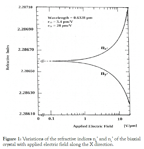
Figure 1: Variations of the refractive indices ny’ and nz’ of the biaxial crystal with applied electric field along the X direction.
Figure 2, shows the variations in the refractive index nx’ against the applied electric field. As shown, nx’ drops off following a trend similar to that of ny’. Since the refractive indices nx’, ny’, nz’ depicted in Figures 1 and 2 are remarkably different, it is concluded that, as the consequence of application of an electric field along the x principal axis, the initially uniaxial lithium niobate crystal has been perturbed into a biaxial one.
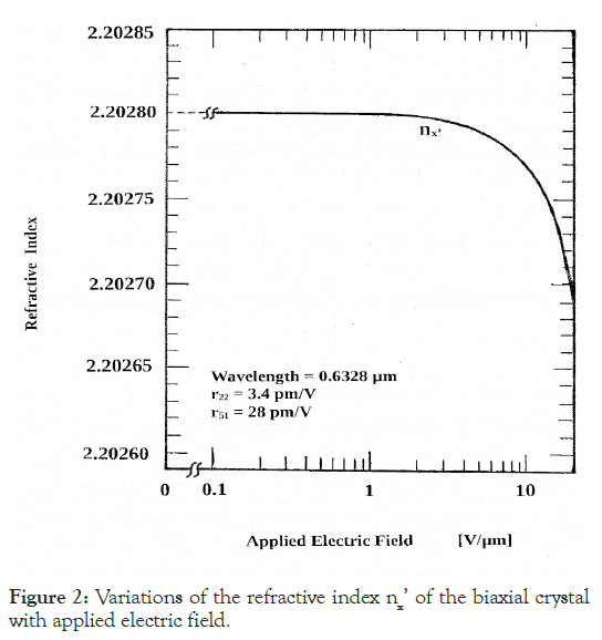
Figure 2: Variations of the refractive index nx’ of the biaxial crystal with applied electric field.
With respect to the principal axes of the perturbed biaxial lithium niobate crystal, variations in the inclination of the principal axis x’ with respect to the optical z-axis of the uniaxial crystal shown by β is depicted in Figure 3. It can be concluded that these principal axes were rotated by approximately 45° over the entire range of applied electric fields. Such a rotation would be approximately δ=42° (in the transverse plane) at large applied electric fields. In the literature, a 45° rotation of the principal axes was reported for an applied electric field along the optical axis of a Potassium Dihydrogen Phosphate (KDP) [4]. Under these circumstances, light propagation along the optical axis of such crystals is impeded and the use of transparent electrodes becomes mandatory, together with the disappearance of the advantages of the form factor. In this regard, rotation of the principal axes by approximately 45° in a transverse plane accompanied by light propagation along the optical axis, is achieved for the first time.
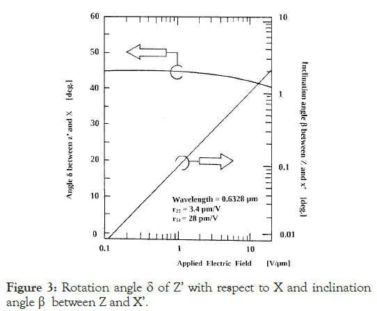
Figure 3: Rotation angle δ of Z’ with respect to X and inclination angle β between Z and X’.
In lieu of the above explanations, one may look at the relative orientations of the principal axes x’, y’, z’ with respect to the x, y, z, coordinates of the uniaxial crystal, as depicted in Figure 4.
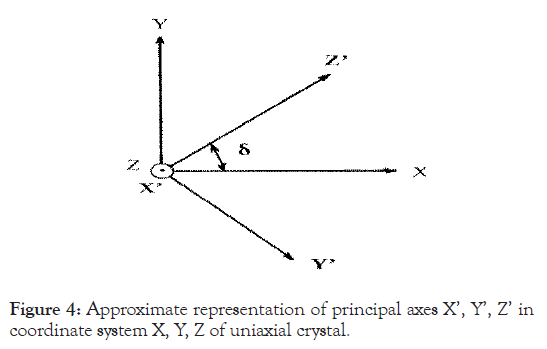
Figure 4: Approximate representation of principal axes X’, Y’, Z’ in coordinate system X, Y, Z of uniaxial crystal.
As the inclination of x’ with respect to z is, utmost 1° according to Figure 3, it is considered to be approximately perpendicular to the xy plane. The mutually perpendicular y’ and z’ principal axes are, to a good approximation, in the xy plane but rotated by the angle δ which is not significantly different from 45°. These achievements (depicted concisely in Figure 4) have significant applications in optical devices. The orientations of the principal axes suggest that the initial uniaxial crystal evolves into a biaxial crystal but with one principal axis maintained almost along the optical axis. The remaining two principal axes lie in a plane transverse to the optical axis but rotated by approximately 45°. This relative orientation is maintained over the entire range of applied electric fields. As an application, a fast spatial light switch is disclosed wherein an incident plane-wave light with a linear polarization along x is rotated to a new polarization along y, in association with propagation along the optical axis [9]. Typically, a 90° plane-wave polarization rotation is required in many applications. This can easily be achieved by adjusting the propagation length (along the optical axis) of a lithium niobate crystal, as shown in Figure 5, where the input light is considered to be a plane-wave.
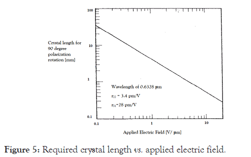
Figure 5: Required crystal length vs. applied electric field.
As shown, the variations in required crystal length with applied electric field follow a straight line. For example, at an applied electric field of 1 V/μm, a 4.2 mm long lithium niobate crystal can alter the light of linear polarization along x to that along y. The important point to note is that, because Pockels activity is a very fast phenomenon, such rotation can reach speeds in excess of several tens of GHz and possibly up to 100 GHz, depending on the propagation length and availability of high-voltage sources. Such fast 90° polarization rotation in the transverse plane is expected to find numerous applications in optical devices and systems. It is important to note that losses in quality lithium niobate crystals are small. Since propagation lengths less than ~1 cm are considered, the absorption losses have been neglected in the presented results.
In summary, when an electric field is applied along the x principal
axis of a uniaxial crystal of trigonal  point group symmetry,
the crystal evolves into a biaxial crystal exhibiting 3 distinct
refractive indices. One of the principal axes of the biaxial crystal
lies approximately along the optical axis. The remaining two
principal axes rotate, in the transverse plane, by approximately
45°. The polarization direction of an x-polarized plane wave
input-light rotates when propagating along the principal axis. The
required crystal length in achieving 90° polarization rotation is
determined.
All relevant data are within the paper and its supporting file.
Citation: Nayyer J (2024). Optical Properties of Uniaxial Trigonal Crystals of  Point Group Symmetry under an Applied Electric Field along X
Principal Axis. J Phys Chem Biophys.14:400.
Received: 10-Sep-2024, Manuscript No. JPCB-24-33939; Editor assigned: 12-Sep-2024, Pre QC No. JPCB-24-33939 (PQ); Reviewed: 26-Sep-2024, QC No. JPCB-24-33939; Revised: 03-Oct-2024, Manuscript No. JPCB-24-33939 (R); Published: 10-Oct-2024 , DOI: 10.35841/2161-0398.24.14.400
Copyright: © 2024 Nayyer J. This is an open-access article distributed under the terms of the Creative Commons Attribution License, which permits unrestricted use, distribution, and reproduction in any medium, provided the original author and source are credited.