Journal of Pollution Effects & Control
Open Access
ISSN: 2375-4397
ISSN: 2375-4397
Research Article - (2016) Volume 4, Issue 4
Conventionally, freshwater has been the only source of water for processes used in the industries due to the fact that it is cheap, and the wastewater generated in these processes has been treated in a central common facility in order to remove contaminants and to meet regulatory specifications for wastewater disposal. This research identify an optimum design of water reuse network for Kaduna refinery and petrochemical company (KRPC), while considering suspended solid (SS), hardness (H, Chemical oxygen demand (COD) and Free hydrocarbons (FH) wastewater contaminants and analysing the feasibilities of reuse and recycling for water and wastewater minimization in the water network of the company by using graphical method known as Water Pinch Technology (WPT). The analysis indicated the possibility of reducing the fresh water use by 76.8 m3/h (32.3%) if Free Hydrocarbons (FH) was considered as the reference contaminant.
Keywords: Freshwater; Optimization; Wastewater; Environment; Contaminant; Pinch
Large quantity of water is required in many industries, which is used in many processes for washing or as part of the product. The resulting wastewater is usually treated in a central common facility in order to remove contaminants and to meet regulatory discharge requirements. In some cases, the treated wastewater may still contain certain level of pollutants. Consequently, the environmental pollution increases due to this disposal trend. As opposed to this conventional approach, reusing and re-routing the water streams in an integral water network helps in reducing the consumption of freshwater, and minimizes the amount of wastewater to be treated and disposed of to the environment. This is very important, especially in developing countries where the relatively high cost and limited manpower pose additional challenges to effective wastewater treatment. One of the methods that can be used to minimise wastewater production is by Graphical method known as Water Pinch Technology (WPT) or Water Pinch Analysis (WPA).
WPT or WPA originates from the concept of heat pinch technique. It is a systematic technique for reducing water consumption and wastewater generation through integration of water-using activities or processes. It was first introduced by Wang and Smith. They used a limiting composite curve to solve water minimization problems. Since then, it has been widely used as a tool for water conservation in industrial process plants. It was extended in 1998 by Nick Hallale at the University of Cape Town, who developed it as a special case of mass exchange networks for capital cost targeting. Manan et al. [1] applied it successfully in urban/domestic buildings. Most of the methods used in WPT/WPA are based on the mass exchange of one or several contaminants. If the mass exchange is based on mass transferring of one contaminant, the problem will be solved as a single contaminant [2-4]. Nevertheless, if it includes mass transferring of two or more key contaminants, the problem will be solved as multiple contaminants [5]. Graphical methods are so practical to solve single contaminant problems. However, they are complicated and sometimes impossible for multiple contaminant problems [6].
This paper focuses on wastewater minimisation using single contaminant technique using WPT/WPA based on the composite curves introduced by Wang and Smith [7] and the work of Mohammadnejad et al. [6]. Furthermore, it will address the problem of an optimum design of water minimization by using a combination of WPA, simple mathematical calculation and possible forbidden or forced water network interconnections restrictions. The proposed method tries to addresses shortcomings in the conventional WPA by considering the possibility of interconnections of different processes in any industry [8,9]. The method thus represents an improvement over existing stateof- the-art approaches. This paper will also test the feasibility of the method using data obtained from the Nigerian Kaduna petrochemical refinery. The feasibilities of reuse and recycling of water and wastewater minimization in the water network of the refinery will be analysed by considering suspended solid (SS), hardness (H), chemical oxygen demand (COD) and Free Hydrocarbons (FH) wastewater contaminants [10,11].
This will eventually lead to providing a means of minimizing the potential dangers facing the aquatic ecosystem as a result of the reduction in the discharge volume of industrial effluents containing harmful contaminants in concentrations above the maximum permissible levels and facilitate efficient and cost effective water usage planning and management.
This research is on the Kaduna Refining and Petrochemical Company Limited (KRPC) (Figure 1), a Subsidiary of Nigerian National Petroleum Corporation (NNPC).
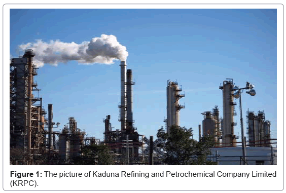
Figure 1: The picture of Kaduna Refining and Petrochemical Company Limited (KRPC).
The Refinery project was completed and the Fuels Plant was commissioned in 1980. While the two other subsections of the refinery, the Lubes Plant and Petrochemical Plant were commissioned in 1983 and 1988 respectively. Kaduna Refinery occupies an area of 2.89 square kilometres. The plot plan is designed with safety and ease of maintenance in mind. The design also attempts to minimize operating costs. The refinery was designed to process both imported paraffinic and Nigerian crude oils into fuels and lubes products and was constructed by Chiyoda Chemical Engineering and Construction Company (now Chiyoda Corporation) of Japan (http://www.nnpcgroup.ng/KRPC.aspx.htm, 2015). The total installed capacity of the refinery is 110,000 BPSD. The water usage network existing in KRPC shows that fresh water from the river is the only source of water for process and other utilities use. The typical characteristics of this water are high suspended solids (with seasonal variation), high dissolved solids (metals), and variable turbidity. From the information obtained, the flow rate of the fresh water use is 650 m3/h. The existing water usage network by various units is shown in Figure 2.
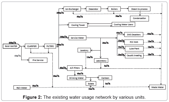
Figure 2: The existing water usage network by various units.
Table 1 shows the flow rate and the maximum allowable concentration at inlet (Cin) and outlet (Cout) of major water using units. However the value for fire unit indicated as 60.0 m3/h may reach 150.0 m3/h during fire fighting.
| Unit No. | Unit name | Flow Rate of Fresh Water (m3/h) | Suspended Solid | Hardness | Chemical Oxygen Demand (COD) | Free Hydrocarbons | ||||
|---|---|---|---|---|---|---|---|---|---|---|
| Cin (ppm) | Cout (ppm) | Cin (ppm) | Cout (ppm) | Cin (ppm) | Cout (ppm) | Cin (ppm) | Cout (ppm) | |||
| 1 | Cooling Tower | 150 | 40 | 500 | 5 | 10 | 0 | 150 | 0 | 5 |
| 2 | Ion Exchangers | 280 | 10 | 20 | 20 | 100 | 0 | 150 | 0 | 5 |
| 3 | Laboratory | 20 | 25 | 250 | 50 | 200 | 400 | 1000 | 0 | 5 |
| 4 | SWS Desalters | 45 | 30 | 300 | 20 | 100 | 400 | 1000 | 0 | 1000 |
| 5 | FCC SWS | 15 | 15 | 30 | 20 | 100 | 600 | 1200 | 0 | 10 |
| 6 | Caustic treating | 10 | 15 | 20 | 20 | 100 | 600 | 1200 | 0 | 10 |
| 7 | Drinking | 60 | 20 | 150 | 10 | 200 | 0 | 0.05 | 0 | 0 |
| 8 | Fire | 60 | - | - | - | - | - | - | - | - |
Table 1: The maximum allowable value of major water using units.
Water pinch analysis steps
Water Pinch Analysis (WPA) was carried out using source and sink composite curves, which is a graphical tool for setting water recovery targets as well as for design of water recovery networks [12]. It considers each water-using operation as being described by the mass transfer of a certain contaminant(s) from the process itself to the water stream (Figure 3a) and represented by the Loading and Concentration Figure (Figure 3b). First of all, in order to achieve a better understanding of the composite curves, a single water using unit is analysed in this section.
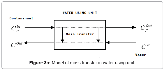
Figure 3a: Model of mass transfer in water using unit.
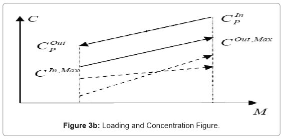
Figure 3b: Loading and Concentration Figure.
WPA involves five key steps as stated by Wan and Manan [13], they are:
1. Analysis of water network: The first step is to analyse the existing or the base case water network through plant auditing as shown in Figure 2. In general, water-using operations can be classified into two main categories, i.e., mass-transfer-based (MTB) and non-mass-transfer-based (NMTB) operations [1,14].
2. Data extraction: The second step is to identify water sources and water sinks having potential for reuse and recycling and to extract the limiting water flow rate and limiting concentration data. Non-limiting concentrations in the water system are situated at a concentration below their maximum limits and do not affect the water sink for that operation.
3. Setting the minimum utility targets: The third step is to establish the minimum possible quantity of fresh water requirement and wastewater generation, or the minimum water targets using a targeting method.
4. Water network design/retrofit: The fourth step is to design a water recovery network to realise the minimum water targets.
5. Economic evaluation: The final step is to evaluate the economics of the water network.
The processes that use large amount of water rate such as cooling tower, Ion exchangers, and Service water used in desalter, fuel carbon cracking, Lube plant, caustic treating and laboratory in the refinery were selected [15-19]. They use total rate of 565 m3/h which is equivalent to 82.5% of the total water rate used by the refinery. While the contaminants selected are Suspended solids (SS), Hardness (H), Chemical oxygen demand (COD) and free hydrocarbons (FH).
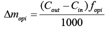
These contaminants are analysed separately using single contaminant method of WPA/WPT, by establishing the pinch point using mass load which is calculated as follows (Equation 1):
 (1)
(1)
Where Δmopi is the mass-load for operation i, Cout and Cin are the outlet and inlet concentration respectively, and fopi is the fresh water flowrate.
The Schematic representation of water balance superstructure model of KRPC water using operations in all processes is illustrated in Figure 4. This can be used as the bases for analysis of water using single contaminant method.
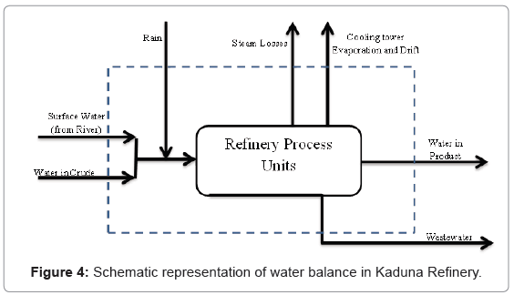
Figure 4: Schematic representation of water balance in Kaduna Refinery.
Water Pinch Analysis (WAP) using single contaminant method
The WAP analysis using single contaminant method is done by constructing limiting composite curve (LCC). To construct the LCC, limiting water profiles of individual processes are plotted on an impurity concentration vs load graph. The limiting water profiles are plotted according to their limiting inlet and outlet concentrations which define the concentration intervals. The impurity load is then added within each concentration interval to form the limiting composite curve [20-25].
The limiting water use data for suspended solids (SS), Hardness (H), Chemical oxygen demand (COD) and free hydrocarbons (FH) contaminants and their calculated cumulative mass load (ppm) are shown in Tables 2-5 respectively. The data were established by referring to the water consuming units as sink and water generating units as source and it was used to construct the limiting composite curves which indicate the pinch point for the particular contaminant considered as a single contaminant to all the processes [26-28]. The sink and source were arranged in ascending order from lower contaminant value process to the higher one. The curves are shown in Figures 5-8.
| Process number | Sink | Sink Flow Rate | Cin (ppm) | Source | Source Flow Rate m3/h | Cout(ppm) | Mass Load | Cummulative Mass Load (ppm) | Cumulative Flow |
|---|---|---|---|---|---|---|---|---|---|
| m3/h | (ppm) | m3/h | |||||||
| 8 | SK8 | 60 | - | SR8 | 60 | - | - | - | 60 |
| 2 | SK2 | 280 | 10 | SR2 | 280 | 20 | 2.8 | 2.8 | 340 |
| 5 | SK5 | 15 | 15 | SR5 | 15 | 30 | 0.225 | 3.025 | 355 |
| 6 | SK6 | 10 | 15 | SR6 | 10 | 20 | 0.05 | 3.075 | 365 |
| 7 | SK7 | 60 | 20 | SR7 | 60 | 150 | 7.8 | 10.875 | 425 |
| 3 | SK3 | 20 | 25 | SR3 | 20 | 250 | 4.5 | 15.375 | 445 |
| 4 | SK4 | 50 | 30 | SR4 | 45 | 300 | 12.15 | 27.525 | 490 |
| 1 | SK1 | 150 | 40 | SR1 | 150 | 500 | 69 | 96.525 | 640 |
Table 2: Limiting water data for suspended solid (SS) contaminant.
| Process number | Sink | Sink Feed Flow Rate m3/h | Cin (ppm) | source | Source Flow Rate m3/h | Cout(ppm) | Mass load | Cummulativemassload (ppm) | cumulative flow |
|---|---|---|---|---|---|---|---|---|---|
| (ppm) | m3/h | ||||||||
| 1 | SK1 | 150 | 5 | SR1 | 150 | 10 | 0.75 | 0.75 | 150 |
| 2 | SK2 | 280 | 20 | SR2 | 280 | 100 | 22.4 | 23.15 | 430 |
| 4 | SK4 | 45 | 20 | SR4 | 45 | 100 | 3.6 | 26.75 | 475 |
| 5 | SK5 | 15 | 20 | SR5 | 15 | 100 | 1.2 | 27.95 | 490 |
| 6 | SK6 | 10 | 20 | SR6 | 10 | 100 | 0.8 | 28.75 | 500 |
| 7 | SK7 | 60 | 10 | SR7 | 60 | 200 | 11.4 | 40.15 | 560 |
| 3 | SK3 | 20 | 50 | SR3 | 20 | 200 | 3 | 43.15 | 580 |
| 8 | SK8 | 60 | - | SR8 | 60 | - | - | - | 640 |
Table 3: Limiting water data for hardness (H).
| Process number | Sink | Sink Feed Flow Rate m3/h | Cin (ppm) | Source | Source Flow Rate m3/h | Cout(ppm) | Mass load | Cumulative massload (ppm) | Cumulative flow |
|---|---|---|---|---|---|---|---|---|---|
| (ppm) | m3/h | ||||||||
| 7 | SK7 | 60 | 0 | SR7 | 60 | 0.05 | 0.003 | 0.003 | 60 |
| 1 | SK1 | 150 | 0 | SR1 | 150 | 150 | 22.5 | 22.503 | 210 |
| 2 | SK2 | 280 | 0 | SR2 | 280 | 150 | 42 | 64.503 | 490 |
| 3 | SK3 | 20 | 400 | SR3 | 20 | 1000 | 12 | 76.503 | 510 |
| 4 | SK4 | 45 | 400 | SR4 | 45 | 1000 | 27 | 103.503 | 555 |
| 5 | SK5 | 15 | 600 | SR5 | 15 | 1200 | 9 | 112.503 | 570 |
| 5 | SK6 | 10 | 600 | SR6 | 10 | 1200 | 6 | 118.503 | 580 |
| 8 | SK8 | 60 | - | SR8 | 60 | - | - | 640 |
Table 4: Limiting water data for chemical oxygen demand (COD).
| Process number | Sink | Sink Feed Flow Rate m3/h | Cin (ppm) | Source | Source Flow Rate m3/h | Cout(ppm) | Mass load | Cumulative massload (ppm) | Cumulative flow |
|---|---|---|---|---|---|---|---|---|---|
| (ppm) | m3/h | ||||||||
| 7 | SK7 | 60 | 0 | SR7 | 60 | 0 | 0 | 0 | 60 |
| 1 | SK1 | 150 | 0 | SR1 | 150 | 5 | 0.75 | 0.75 | 210 |
| 2 | SK2 | 280 | 0 | SR2 | 280 | 5 | 1.4 | 2.15 | 490 |
| 3 | SK3 | 20 | 0 | SR3 | 20 | 5 | 0.1 | 2.25 | 510 |
| 5 | SK5 | 15 | 0 | SR5 | 15 | 10 | 0.15 | 2.4 | 525 |
| 6 | SK6 | 10 | 0 | SR6 | 10 | 10 | 0.1 | 2.5 | 535 |
| 4 | SK4 | 45 | 0 | SR4 | 45 | 1000 | 45 | 47.5 | 580 |
| 8 | SK8 | 60 | - | SR8 | 60 | - | - | - | 640 |
Table 5: Limiting water data for free hydrocarbons (FH).
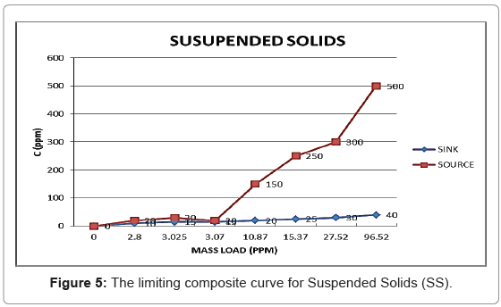
Figure 5: The limiting composite curve for Suspended Solids (SS).
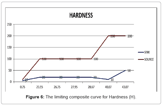
Figure 6: The limiting composite curve for Hardness (H).
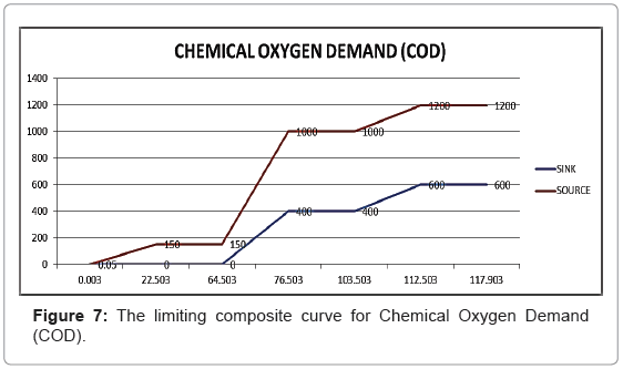
Figure 7: The limiting composite curve for Chemical Oxygen Demand (COD).
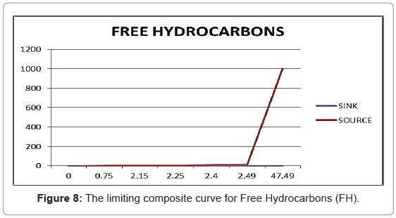
Figure 8: The limiting composite curve for Free Hydrocarbons (FH).
Figure 5 is the graphical representation of limiting water use data for suspended solids (SS) in Table 2. The graph indicates a pinch point at 20 ppm concentration of SS, and 3.07 ppm cumulative mass load. This means that there is possibility of reduction of fresh water source of 365 m3/h if SS was considered as the only contaminant in the refinery water supply, which is 56% of the total fresh water use.
Figure 6 is the graphical representation of limiting water use data for hardness (H). The graph indicates a pinch point at 100 ppm concentration of H, and 23.15 ppm cumulative mass load. This means that there is possibility of reduction of fresh water source of 430 m3/h if H was considered as the only contaminant in the refinery water supply, which is 66% of the total fresh water use.
Figure 7 is the graphical representation of limiting water use data for Chemical oxygen Demand (COD). The graph indicates a pinch point at 150 ppm concentration of COD, and 64.5 ppm cumulative mass load. This means that there is possibility of reduction of fresh water source of 490 m3/h if COD was considered as the only contaminant in the refinery water supply, which is 75.4% of the total fresh water use.
Figure 8 is the graphical representation of limiting water use data for Free Hydrocarbon (FH). The graph indicates a pinch point at 10 ppm concentration of FH, and 2.49 ppm cumulative mass load. This means that there is possibility of reduction of fresh water source of 534 m3/h if FH was considered as the only contaminant in the refinery water supply, which is 82% of the total fresh water use, because of the range of acceptance of pollution level of FH by different processes.
The result obtained by this graphical analysis of pinch point can be justified by analysing the concentration grid of each contaminant and considering that a water generating process with output concentration lower than the minimum input concentration of another process can be re-used if the process allow re-use of water from another process [26].
The concentration grid for suspended solids (SS) contaminant is shown in Figure 9. The result indicate that water from three processes namely; Ion Exchangers, FCC SWS, Caustic treating and Drinking can be re-used in the refinery which gives a total saving of fresh water source of 365 m3/h if SS is considered as the only contaminant as shown by the pinch graphical analysis. This agrees with the result obtained from WPT analysis [29-31].
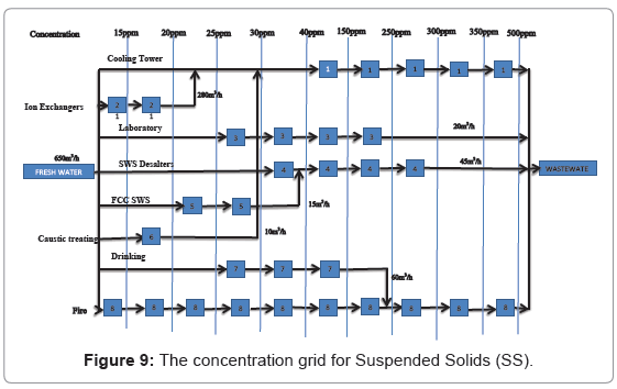
Figure 9: The concentration grid for Suspended Solids (SS).
The concentration grid for Hardness (H) contaminant is shown in Figure 10. The result indicate that only water from Cooling Tower and Drinking can be re-used in the refinery which gives a total saving of fresh water source of 210 m3/h if H is considered as the only contaminant, which is 32.3% of the total fresh water use. This contradicts the value shown by the pinch graphical analysis. Possibly due to the presence of four processes (Ion Exchangers, SWS Desalter, FCC SWS, and caustic treating) that has equal concentration ranges of 20 ppm to 100 ppm.
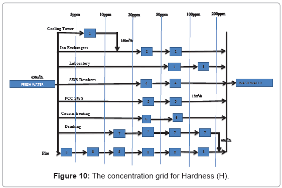
Figure 10: The concentration grid for Hardness (H).
Furthermore, the concentration grid for Chemical Oxygen Demand (COD) contaminant is shown in Figure 11. The result indicate that water from three processes namely; Cooling Tower, Ion Exchangers, and Drinking can be re-used in the refinery which gives a total saving of fresh water source of 490 m3/h if COD is considered as the only contaminant as shown by the pinch graphical analysis.
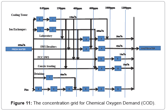
Figure 11: The concentration grid for Chemical Oxygen Demand (COD).
The concentration grid for Free Hydrocarbons (FH) contaminant is shown in Figure 12. The result indicate that only water from Drinking can be re-used in the refinery which gives a total saving of fresh water source of 60 m3/h if FH is considered as the only contaminant, which is 9.2% of the total fresh water use. This contradicts the value shown by the pinch graphical analysis. Possibly due to the fact that all the processes have equal input concentration ranges of 0 ppm.
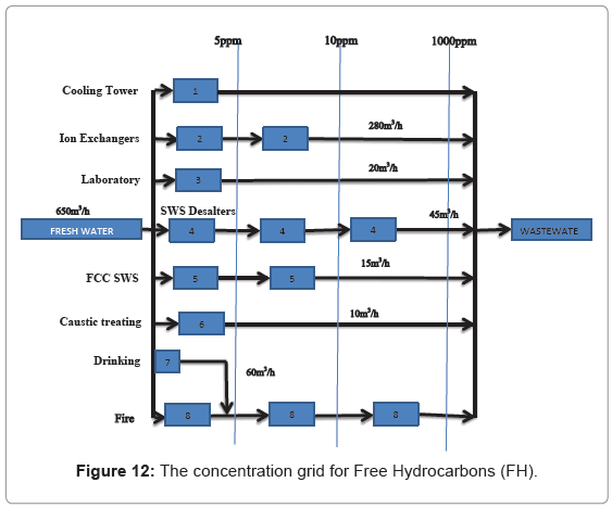
Figure 12: The concentration grid for Free Hydrocarbons (FH).
Therefore, the pinch analysis for a single contaminant should be used only in the situation where all the processes have different concentration ranges. Otherwise equal concentration ranges should be eliminated before carrying out the analysis.
Based on the above analysis of single contaminant, the amount of fresh water can be reduced by re-using 365 m3/h (56%) if SS was considered as the only contaminant, in the refinery water supply, by 210 m3/h (32.3%) if H was considered as the only contaminant, by 490 m3/h (75.4%) if COD was considered as the only contaminant, and by 60 m3/h (9.2%) if FH was considered as the only contaminant.
In this paper, an optimum design of water reuse network for Kaduna refinery by considering suspended solid (SS), hardness (H), chemical oxygen demand (COD) and Free Hydrocarbons (FH) wastewater contaminants was achieved. The analysis of the feasibilities of reuse and recycling for water and wastewater minimization in the water network of the refinery was also carried out. The result indicate that there are possibilities of reduction of fresh water use of 365 m3/h, 430 m3/h, 490 m3/h, and 534 m3/h if SS, H, COD, and FH are considered as the single-contaminant in the refinery water supply, respectively. This will leads to 56%, 66%, 75.4%, and 82% reduction of the total fresh water use if SS, H, COD, and FH are considered as the singlecontaminant in the refinery water supply, respectively. However, these results were further analysed by using the concentration grid of each contaminant. The values obtained for SS and COD agree with the result obtained from WPT analysis, but give the values of 210 m3/h and 60 m3/h, which correspond to the reduction of 32.3% and 9.2% for H and FH respectively.