Journal of Physical Chemistry & Biophysics
Open Access
ISSN: 2161-0398
ISSN: 2161-0398
Research Article - (2024)Volume 14, Issue 5
The Semiconductor and Liquid Assisted Photothermal Effect (SLAPE) concept was employed for the first time in this study to generate electricity from sunlight. In SLAPE process, a semiconducting material is immersed completely in a stable organic solvent to capture the sunlight reaching the earth surface completely and to turn it into the heat-energy, which can be eventually converted into electricity with the help of a heat engine and electric generator. The SLAPE solar panels were fabricated with top and bottom chambers separated by a thin thermally conducting metal sheet (Cu or Al). Upon exposure of a one square meter area SLAPE solar panel containing 21 numbers of silicon photovoltaic cells together with 2 litres γ-butyrolactone to the sunlight for about 2 hours generated about 17 V electricity with the help of a laboratory model reciprocally moved steam engine and a custom-made electric generator, whereas, a commercial SPVC solar panel with same 21 number SPVCs generates a maximum voltage of 11 V only. The theoretical background governing the SLAPE solar panels, the necessity for this invention and the establishment of the proof of concept of SLAPE solar panels have been thoroughly presented and discussed in this article.
Electricity; Sunlight; Semiconductor; Silicon photovoltaic cell solar panels; Renewable and sustainable energy; γ-butyrolactone
Today, the development of a simple, inexpensive and efficient process for producing electricity from sunlight and use of that electricity to convert the waste-steam greenhouse CO2 gas into energy rich solar-fuels and to split water into H2 and O2 gases, which is popularly called as an “Artificial Photosynthesis (AP), have been considered as one of the top-most research priorities across the globe as these processes can solve the problems related to i) securing the self-sufficiency in energy production by each and every country, ii) the CO2 associated global warming and the resultant social cost of carbon, iii) the storing of renewable (and surplus) energy in an high-energy-density carbon-neutral liquid-fuels such as, methanol so that they can be directly employed in place of diesel and petrol in the present existing energy distribution infrastructure (i.e., in the Internal Combustion (IC) engines) so that there would not be any severe economic consequences while transforming from fossil fuel energy dependency to non-fossil fuel, renewable and solar energy dependency and iv) depletion of fossil fuels mainly the crude oil, which is an important resource of several commodity chemicals required for the future generations. Efficient sunlight-toelectricity conversion technology can eliminate up to 8%-15% power transmission losses that are associated with the gridconnected electricity produced at remote places far from the densely populated cities by burning fossil fuels (i.e., coal, natural gas and crude oil) at thermal power plants. In fact, as on today, the synthesis of liquid-fuels from CO2 and splitting of water into H2 and O2 gases using electricity derived from sunlight in electrochemical cells can be considered as one of the most effective and economic way of storing energy to circumvent the daily and seasonal intermittency of solar energy as the energy stored in H2 and O2 gases or CO gas can be taken back again as and when required on a demand basis using fuel cells. In fact, today, the fossil fuels are the main energy resource supplying to meet >85% of the primary energy requirement of all most all developed and developing countries except very few countries including France and Germany and their usage has been found to be responsible for raising the concentrations of CO2 in the atmosphere and for the resultant global warming as well as for the social cost of carbon problems [1].
It is a well-known fact that nature stores solar energy to feed not only 8 billion people but also the entire life living today on our planet in the Natural Photosynthesis (NP) process by using CO2 and water as energy storing materials. In fact, the NP process is nothing but the storing of solar energy by using CO2 and water as energy storing materials by following a natural photosynthesis process in the form of food materials and bio-mass to feed human beings and animals. The solar energy stored in the form of food materials (i.e., grains) can be preserved and used as and when required on a demand basis. The natured stored solar energy in the form of food materials need not have to be used immediately like the electricity produced from sunlight by using SPVC solar panels needs to be used. Furthermore, the amount of solar energy stored by plant leaves in the form of food material and bio-mass in the NP process cannot be stored in any of the manmade existing energy storing devices including the most advanced lithium ion batteries and capacitors as it would be prohibitively expensive.
Nature clearly suggests that any amount of energy can be stored by using CO2 and water as energy storing materials while beneficially contributing to the environment. In fact, the fossil fuels are nothing but solar energy stored by the nature. The fuel chemicals synthesized in AP by using electricity derived from sunlight are called as solar fuels, which are exactly similar to fossil fuels. The only difference between the fossil and solar fuels is the former ones are created by the nature from bio-mass in which the solar energy was stored by plant leaves using CO2 and water as energy storing materials at the rate of 0.2%, whereas, the solar-fuels, have to be synthesized by following manmade technologies by electrochemically reducing CO2 and splitting water using electricity derived from sunlight to meet all the energy needs of the society with a minimum (conversion) efficiency >10% so that these processes can be practiced at industry with economic viability. Hence, the entire energy distribution infrastructure available today to use fossil fuels can also be used for solar fuels formed in AP process as well. Thus, the renewable liquid-fuel chemicals produced from CO2 gas in AP process can indeed replace the fossil fuels in all their current uses such as, powering industrial processes, machinery and transportation, etc. In fact, the AP process can establish a closed-loop CO2 cycle that turns the conventional fuels into the “green energy vectors”. Furthermore, the energy density of electricity storing batteries is far too low for most of the power-intensive applications (about 1%-2%) in comparison to those can be stored in carbon-based fuels (50 MJ/kg with methane, methanol, diesel and gasoline). In fact, the e-batteries such as Li-ion batteries are best suitable and opt for low-energy required portable devices such as, mobile phones, laptops, etc., but not for high-energy intensive applications such as, heavy duty vehicles, buses, lorries, trucks, aero planes, etc. Furthermore, batteries also have certain limitations with respect to their cost, service life, recharging time, involvement of hazardous and polluting materials, etc [2].
Once a suitable and inexpensive method for converting sunlight into electricity is developed and thus, obtained electricity is suitably utilized to convert the waste-stream greenhouse CO2 gas into CO and the water into H2 and O2 gases, all most all countries can use solar energy to meet all their energy requirements without depending on foreign countries to import the fossil fuels while meeting all the deadlines imposed by Intergovernmental Panel on Climate Change (IPCC) and United Nations Framework Convention on Climate Change (UNFCCC) as far as environmental safety and release of CO2 gas into the atmosphere are concerned. Upon implementing such an AP process worldwide, in about 10 to 15 years period, a lot of fossil fuels burned so far to meet the energy requirement of the society can be restored in the form of natural gas at all the sea shores across the globe as no CO2 is freshly released into the atmosphere in large quantities as CO2 present in the atmosphere is consumed by the plant leaves so that its concentration will come down to those levels (i.e., about 280 ppm) present in the atmosphere prior to the industrial revolution started during period of around 1750 to early 1800 century. Once, this target is reached, the unseasonal and unexpected heavy rains and floods that are occurring these days can be minimized, which are disturbing the functioning of society for several days together in certain cities like those recently occurred in Chennai city in the year 2015 and Kerala in the year 2018 [3].
In view of the above reasons, the development of a simple, easy to fabricate and inexpensive method to produce electricity from sunlight and using thus obtained electricity to drive the reactions of AP are of utmost important to solve both energy and environment related problems. For example, today, India alone has 118 thermal power plants, 220 cement industries, 650 steel plants (including those small scale industries) and 18 public sector refineries and 5 refineries in the private sector/or as a joint venture, the largest refineries being RIL Jamnagar (Gujarat), NEL Vadinar (Gujarat) and IOC Panipat (Haryana). All these industries together everyday generate several million tons of CO2 gas by burning fossil fuels such as, oil, coal and natural gas to meet the energy needs of the society and all thus generated CO2 gas is released into the atmosphere. Once, an inexpensive and simple to fabricate solar panels to produce electricity from sunlight are developed to drive the reactions of AP efficiently at lower processing cost, then by following that process all the CO2 generated at major outlets across the globe can be converted into CO gas initially and then into methanol, diesel and synthetic petrol. The IPCC and UNFCCC are responsible for pledging 197 countries (as on December 2015) to take the responsibility to stabilize the greenhouse CO2 gas concentration in the atmosphere at a level that would prevent dangerous anthropogenic interference with the climatic system. Furthermore, for example, according to IPCC and UNFCCC by 2030, the European Union (EU) has to meet ≥ 27% of their primary energy requirement from the renewable energy resources, which ensures up to 40% reduction in Greenhouse Gas (GHGs) emissions in comparison to 1990 levels. Today, EU gets about 50% of its primary energy from the imported fossil fuels. In EU, the buildings are the leading consumers of energy (40%), ahead of transportation (32%), industry (27%) and agriculture (2%). Heating is at top of the consumption list accounting for 65% of domestic energy use. As a result, 33% of the total CO2 emissions in EU come from fossil fuels used for heating purposes only. Only ~17% of the total energy requirement is met by the electricity and out of which about 11.7% is met from hydroelectric power [4].
There are two ways to control the CO2 associated global warming problem. One is to replace the fossil fuels usage with renewable energy vectors such as, solar energy and the other one is to find out the solutions to solve the CO2 associated global warming problem. Today, the readily available technology to solve the CO2 associated global warming problem is the “CO2 sequestration”, which is also known as the “Carbon Capture and Storage (CCS)” process. This latter process is not only expensive but also quite cumbersome. As a part of the CCS process, the CO2 captured at various outlets such as, thermal power plants, cement industry, steel factories, gas refineries, etc., is transported and pumped mainly into the deep seawater below 3500 meters. At 3500 meters deep in the sea, a pressure of >350 bar and a temperature of ~3°C exist. When CO2 is exposed to these conditions, it turns into CO2 clathrate, which is a snowlike crystalline substance, composed of H2O ice and CO2. Nevertheless, its long term stability is still a debatable subject. It is also a known fact that the CO2 capturing sites are most often far away from those sites normally used for CO2 sequestration. In certain places like those in Europe, CO2 transportation in pipelines to the storage sites is quite difficult and it will increase the cost of the process by at least 15%-20%, which is considered to be unacceptable. The Department of Energy (DoE), USA, suggests that the transportation of CO2 in tankers on road is not acceptable if the distance is more than 100 km. In the total CCS process, about 35%-40% is the transportation and storage costs. This cost would be between 35 €/ton and 50 €/ton for early commercial phase and between 60 €/ton and 90 €/ton during demonstration phase, when transportation of CO2 is made by pipelines for distances not over 200 km-300 km. This cost would be further increased if the transportation is made by road (for example, in certain European countries). Recently, a new CO2 sequestration process was reported, in which when a mixture of water and CO2 was pumped 540 meters deep into the Iceland rocks, this acidic solution causes the leaching of the Mg and Ca metals out of the basalt rocks and converts them into MgCO3 and CaCO3 rocks. These latter rocks have been found to be stable for more than two-year period. The cost of this new CO2 sequestration process has been estimated to be about 18 USD for disposing off a ton CO2 gas. Thus, the CO2 sequestration processes are not only expensive and laborious, they also irreversibly blocks the important C1 carbon resource in the form of CO2 cletherate in deep seawater, which cannot be used for any of the beneficial activities of the human beings. In fact, the CO2 shall be participated in the natural carbon cycle that is required for the sustainability of the life on earth [5].
Alternatively, CO2 can be converted into several value added chemicals and fuels in a process called “Carbon Capture and Utilization (CCU)” with the same expenditure that can be incurred for the CCS process. Sometimes, the value of the product(s) formed in the CCU process can become a bonus as the cost of the products can offset the processing cost to some extent. It is also a known fact that CO2 conversion into fuel chemicals needs thermodynamic energy input apart from those required for overcoming the activation energy barrier. In fact, the high thermodynamic stability of CO2 is responsible for its ability to store the external energy in the form of fuel chemicals synthesized out of it. In fact, the energy spent for overcoming the activation energy barrier is a waste of energy; whereas, the energy spent for overcoming the thermodynamic energy barrier is energy storage. Thus, more amounts of thermodynamic energy requirement means more amount of energy storage in the form of chemical products formed in a particular endothermic reaction. That is the reason why always researchers look for the best catalytic systems to perform a particular reaction to occur via a path that is associated with the least activation energy barrier. Lower the activation energy barrier means lower the amount of energy wastage while driving that particular thermodynamically favorable reaction. The high thermodynamic stability of water (ΔE°=-1.23 V vs. NHE or 1.23 eV) is also responsible for its ability to store 1.23 eV energy in the form of H2 and ½O2 gases formed in electrolysis of water. This same 1.23 eV equivalent electrical energy comes out again when these two gases are reacted in a fuel cell [6].
Even by replacing the usage of the Liquefied Petroleum Gas (LPG) utilized for cooking with the electric stoves driven by electricity derived from sunlight, a significant amount of CO2 gas generation can be avoided. Not only that now-a-days, even the cost of LPG gas has been increasing exorbitantly and without the government aid or subsidy, it has become an unbearable cost for a common man living in India. In Telangana state of India, a 14.2 kg LPG gas cylinder costs about Rs. 1500/- without the Government subsidy and with subsidy, it is about Rs. 950/-. Even the petrol and diesel costs are being increased now-a-days in India very exorbitantly. If all the CO2 gas generated at all its major outlets in India is converted into synthetic petrol using electricity derived from sunlight and used in place of petrol and diesel utilized today to meet the energy requirements, there would be a lot of reduction in the importing of fossil fuels from foreign countries. In fact, an inexpensive way of producing electricity from sunlight and using it for converting CO2 gas produced at all its major outlets into fuel chemicals and for splitting water into H2 and O2 gases can even change the global energy economy and energy dynamics of the world as well. In view of the these and to solve the CO2 associated global warming problem, at the outset, a simple, easy and highly economical method to produce electricity from sunlight is highly essential. Furthermore, to continuously supply the intermittently available solar energy to the society without any back-up from fossil fuels, it is also required to be stored in a well usable form of energy. Fortunately, sunlight is abundant, clean and free and all the world's population living areas also receive the required insolation levels (i.e., 150 watts/m2-300 watts/m2 or 3.5 kWh/m2-7.0 kWh/m2 per day). With this insolation capacity, the required amount of electrical energy can be generated to meet all the needs of the society for buildings using a suitable sunlight to electricity generation technology [7].
The current status of electricity generating processes from sunlight
Today, there are four different types of methods available to generate electricity from sunlight. The first one is Photovoltaics (PVs), which use p-n junctions formed out of a joining of p-type and n-type differently doped silicon semiconductor thin films, the binary III-V GaAs and InP systems, the Copper Indium Gallium Selenide (CIGS), the Perovskite Solar Cells (PSCs) based organic light absorbing chemical compounds such as, Methylammonium Lead Trihalide (MLT) (CH3NH3PbX3, where X is a halogen atom such as iodine, bromine or chlorine), with an optical band-gap between ~1.55 eV and 2.3 eV depending on halide content, etc., which can be amorphous, single or polycrystalline in nature. The second one is the Dye-Sensitized Solar- Cells (DSSCs) (or Gratzel cells) that use cisbis (isothiocyanato) bis (2,2′-bipyridyl-4,4′-dicarboxylato) ruthenium(II), (known as N3 dye), as a light capturing substance. The third one is the thermoelectric effect (i.e., Seebeck and Peltier modules) that uses materials with suitable figure of merit such as, bismuth telluride (Bi2Te3). The fourth one is the concentrated solar radiation or Parabolic Trough Collectors (PTC), which are typically operated at temperatures around 400rugiF( C e 1).
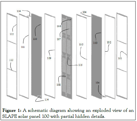
Figure 1: A schematic diagram showing an exploded view of an SLAPE solar panel 100 with partial hidden details.
In Parabolic Trough Collectors (PTC) method, the heat energy captured is utilized by a heat engine (e.g., steam turbine) to produce electricity. The well-known examples of solar thermal power generation using PTCs are the Solar Energy Generating Systems (SEGS) in California, USA. This particular system consists of nine power plants with a total capacity of about 354 Megawatts (MW). However, the price of the electricity generated in this method has been found to be higher in comparison to the one obtained by burning fossil fuels at thermal power plants. The main reason for this high price of the electricity is the utilization of light concentrators, tracking of the light and distribution of electricity from far distances to the utility places. This PTC method has also been found to be quite cumbersome and environmentally and ecologically danger particularly for the survival of the birds in those areas. Alternatively, low temperature solar thermal power generation, which operates using an Organic Rankine Cycle (ORC) offers an increasingly promising for domestic and smaller energy recovery installations when combined with Silicon Photovoltaic Cells (SPVC) for waste-heat utilization. However, these systems are yet to be fully investigated for practical applications and to meet public energy needs [8-10].
The PVs based on CIGS, Perovskites, III-V GaAs and InP systems are either too expensive or not stable and are still being developed in the laboratory. The existing PVs with high-quality III-V semiconductor stacks are associated with costly production steps and are found to be extremely expensive and hardly scalable. More affordable multi-junction PVs made with abundant materials (e.g., based on organic materials, Si and/or perovskites) have not yet shown a significant increase in efficiency relative to the corresponding single-junction technology (i.e., SPVCs), which justifies the efforts in implementing the tandem architectures. Besides, the rigid design of the series-connected subcells has a current output limited by the lowest performing subcell, which further suffers from spectral mismatch losses at non-peak illumination hours or for different geographical locations. The main problem associated with the organic based PSCs is the stability and they are yet to pass the required time period operation test in the real life conditions. The most commonly studied perovskite absorber is Methylammonium Lead Trihalide (MLT). Formamidinum lead trihalide (H2NCHNH2PbX3) with band-gap energies between 1.48 eV and 2.2 eV was also found to be promising for this application. The minimum band-gap shall be closer to the optimal one for a single-junction cell than MLT so that it can exhibit higher efficiencies. The DSSCs suffer from the exorbitant price of the N3 dye used in them, whereas, the efficiencies achieved so far in the thermoelectric modules is very low as materials with the required figure of merit are yet to be identified and/or developed (Figure 2) [11-15].
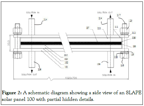
Figure 2: A schematic diagram showing a side view of an SLAPE solar panel 100 with partial hidden details.
Potential of Silicon Photovoltaic Cell (SPVC solar panels
It is a well-known fact that among various methods available today to generate electricity from sunlight, only the SPVC panels are the mostly deployed ones across the globe as a part of producing renewable electricity from sunlight and are in the market for almost last 40 years. In fact, electricity production from sunlight by following Photovoltaic (PV) technology can be considered as a miracle. The SPVC panels provide significant social and environmental benefits as these panels do not generate any Greenhouse Gases (GHGs). The SPVCs are also stand alone and can be integrated, grid-connected and deployed in isolated locations. Furthermore, the semiconductor silicon used in these SPVC panels has an abundant raw material, which is non-toxic, relatively low-cost, allows the fabrication of cells with relatively high and stable Sunlight-to-Electricity (STE) conversion efficiency. It is also the most matured PV material and has been a long-term market leader. In fact, the crystalline silicon (c-Si) technology is widespread and has deep skill and infrastructure not only for PV applications but also for the Integrated Circuit (IC) industries. The number of SPVC panels installed worldwide has grown exponentially since early 2000s and it will be further grown during coming next few decades. By the end of 2015, an estimated 222 Gigawatts (GW) worth of SPVC panels have been installed worldwide. According to a recent report from the International Renewable Energy Agency (IREA), USA, this number could reach to 4,500 GW by 2050. Furthermore, the production cost of SPVC panels has also been diminishing in the last decades, following a learning curve, which is now stagnating.
Although, almost 40 years back the SPVC panels have entered the market and their manufacturing cost has also been came down to the lowest possible level, beyond which it is not possible to go down further, still almost all developed (excluding few countries including Germany, France and Island) and still developing countries including India, meet more than 85% of their primary energy requirement from fossil fuels only. One the main reasons for this is could be as there is no affordable method to store the electricity derived from sunlight for that matter from any of the renewable energy resources and to use it as and when required on the demand basis. At present, the electricity produced from sunlight either needs to be utilized immediately or if it is a surplus one, then it is connected to a grid-system. During the peak hours (only 5-6 hours in a day), if electricity is produced to meet all the energy requirements of the society by using SPVC solar panels, then the electricity generated at thermal power plant is not needed. At that time, the thermal power plant is needed to be shut-down. As during remaining hours (i.e., for almost 19 hours) in a day, the sun is not available, at that time again those associated thermal power plants are required to be switched on. That everyday particularly during summer season switching on and off of thermal power plant has been found to be non-profitable venture in Germany and it incurred huge losses to those operators. Furthermore, the thermal power plants are designed to operate continuously not for intermittent operations.
Fabrication of a SLAPE solar panel
A SLAPE solar panel 100 fabricated by using 21 numbers of SPVCs as semiconducting material, γ-butyrolactone as a nonworking fluid to absorb the sunlight and to generate heat-energy out of the absorbed sunlight in conjunction with SPVCs and Dichloromethane (DCM) as a working fluid along with a blockdiagram showing three major parts utilized by SLAPE solar panels in generating electricity from sunlight. The SLAPE solar panel captures >90% of the sunlight reaching the earth surface and converts it into heat-energy, which can be eventually turned into electricity by using Organic Rankine Cycle (ORC) with the help of an heat-engine and electric generator. The possible beneficial properties of SLAPE solar panels in comparison to those of SPVC solar panels. Each of these two frames were made to have three equally spaced openings for light transmission using two numbers of either flat plate tee (T) shaped or just flat SS-304 bars 113 having dimensions of ~634 mm length × 33 mm width × 5 mm thick that divide that single major rectangular shape frame into three small size rectangular shaped openings. The T-shaped bars 113 at the centre portion of the SLAPE solar panel 100 can be seen from its digital photo. Each of the SS frame was made with 36 numbers of 12 mm diameter (ϕ) holes 125, which are used to hold all the parts of the SLAPE solar panel 100 together while forming two numbers of gas-tight top and bottom chambers with the help of M10 size studs 116 and 117 tightened using two-numbers of nuts 120 on both top and bottom sides after placing both rubber 118 as well as metal 119 washers between the frame and the nuts fitted to the studs (Figure 3).
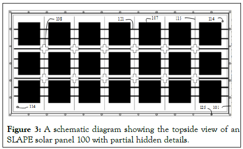
Figure 3: A schematic diagram showing the topside view of an SLAPE solar panel 100 with partial hidden details.
The SLAPE solar panel 100 had with two-numbers of gas tight chambers created by using 3 numbers of Viton 102, 105 and 111 and one Ethylene Propylene Diene Monomer (EPDM) 109 gaskets with dimensions of 15 mm width × 1.5 mm thick. The top chamber is formed between the low-iron containing fully transparent, fully toughened and one-side surface-grooved Borosil solar glass (1480 mm length × 660 mm width × 3.2 mm thick) sheet 110 (supplied by M/s. Gujarat Borosil Ltd., India) placed on top side and a thin and highly thermally conducting 0.5 mm thick Al, 1.1 mm thick or 0.2 mm thick Cu sheet (1480 mm length × 660 mm width) 106 placed on bottom side. Since, the Cu sheet with 0.2 mm is available with only 350 mm width in Hyderabad, India, two sheets of 350 mm width were silver brazed together by keeping them side-by-side to form a 660 mm width and 1480 mm length sheet. The four sides of this gas-tight top chamber is closed with EPDM rubber gasket 109 and to maintain the gap in between top side solar glass sheet 110 and bottom side thermal conducting thin metal sheet 106, 21 numbers of EPDM rubber pieces 108 (~60 mm × 60 mm size cut into plus shape with 20 mm projections) were utilized. The T-shaped flat plate bars used in the construction of SLAPE solar panel does not allow the swelling of the centre portions of the top-chamber when the volume of the low-boiling point DCM working fluid present in the bottom chamber expands by absorbing the in situ generated heat energy by the SPVCs and γ- butyrolactone. In the top chamber, Viton gasket or gapmaintaining pieces cannot be placed as it gets swelled when it comes into contact with γ-butyrolactone NWF 123 solvent employed in the top chamber along with semiconducting materials to capture the sunlight. However, EPDM is quite compatible with the γ-butyrolactone NWF 123 solvent. The 21 numbers of EPDM pieces were joined together using 0.5 mm thick diameter (ϕ) Cu wire 115 and the extended portions of this Cu wires 115 were secured by placing them in between the two SS frames (101 and 112) tightened with nuts and studs. The volumes of these chambers can be varied from 2 litre to 10 litres with the help of two numbers of joints that give three equally spaced opening to the frames 101 and 112 (Figure 4).
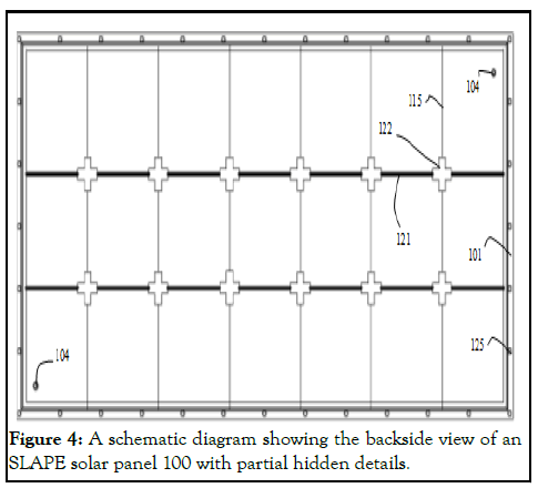
Figure 4: A schematic diagram showing the backside view of an SLAPE solar panel 100 with partial hidden details.
In this top chamber, 21 numbers of multi-crystalline silicon (Si) photovoltaic cells (SPVCs) 107 (15.7 cm × 15.7 cm × <0.25 mm) (Grade A type-P157 × P157, power 18.0%) (supplied by M/s. Adani Solar India, Ahmedabad) interconnected with Sn-Pb (Sn60/Pb40) coated Cu (~1.3 mm width × 0.2 mm thick) (supplied by M/s. the PV connect, IDA Nacharam, Hyderabad) strip 121 were also secured tightly by placing the interconnecting Cu stripes mechanically held in between the SS frames 101 and 112. This top chamber containing SPVCs was filled with either 2.3 litres or 9.6 litres of γ-butyrolactone NWF 123 using 12 mm diameter holes (ϕ) provided on top side solar glass at diagonals and fitted with SS-304 pipes and needle valves 114. 100 mL volume glass syringe with SS needle was used to fill this top chamber with γ-butyrolactone NWF 123 solvent. As soon as, the top chamber is filled with γ-butyrolactone (NWF 123) solvent, the glass syringe with needle was removed and the tightened tierod studs and nuts fully seal the gap so as to not to leak γ- butyrolactone (NWF 123) solvent from top chamber [16].
The gas tight bottom chamber was formed between the top side thin metal sheet 106 and bottom side full toughened soda lime glass sheet 103 (140 mm length × 660 mm width × 5 mm thick supplied b Ms. pafe dlass ptore, ederabad, fndia), which was also provided with two numbers of 12 mm diameter (ϕ) holes at two diagonal ends to fi an pp 304 c lindrical shaped pipes 104 with dimensions of 10 cm length × 12 mm outer diameter × 10 mm inner diameter and one end of the pipe was given with an inner threading to fit a needle valve so as to use it as an inlet and outlet for Working Fluid (WF) 124 Dichloromethane (DCM). To form the gas tight chamber, the Viton rubber gasket 105 was used and to maintain the gap in this chamber, 21 numbers of Viton rubber pieces 122 (21 numbers of ~60 mm × 60 mm size cut into plus shape with 20 mm projections) were utilized. This bottom chamber is filled with Dichloromethane (DCM) WF 124 using inlets and outlets 104. The Viton rubber is quite compatible with Dichloromethane (DCM) WF 124 solvent.
In order to adiabatically seal this the SLAPE solar panel 100 from its surroundings, the top surface of the low-iron containing 3.2 mm thick Borosil solar glass was covered with a 0.13 mm adhesive coated Fluorinated Ethylene Propylene (FEP) film (3D Techno, Gujarat, India; A4 size sheet and without adhesive FEM film with the dimensions of 0.15 mm × 300 mm × 3000 mm), followed by three layers of 0.15 mm thick fully transparent Polyethylene Terephthalate Transparent (PET) plastic sheet and then by another 0.32 mm Borosil low-iron containing solar glass to arrest the heat loss from the top glass and the bottom 5 mm thick sodalime glass 103 surface of the bottom chamber of the SLAPE solar panel 100 was covered by two numbers of 3 mm thick silicone rubber sheet 128 followed by 0.5 mm Stainless Steel (SS) metal sheet 129 in order to minimize the heat losses that occur to the surroundings via convection, convention and radiation processes due to the presence of temperature gradient between the SLAPE solar panel 100 and its surroundings.
The reduction in the intensity of the sunlight from diathermanous material covering given on Borosil solar glass surface has been measured to be less than 15%. These diathermanous covering materials including silicone rubber 128 and metal 129 sheets are not shown in any of the figures for the purpose of clear view of the inner parts of the SLAPE solar panel 100. The pipes and tubes, which make up the conduit in the SLAPE solar panel 100 and the fluid passageways between the various components of the heat generating system are connected and integrated using compression fittings so as to prevent the leaks of both NWF 123 and WF 124. The global normal transmission coefficient of 3.2 mm thick Borosil solar glass sheet 110 is about 0.91. Usually, for double-side anti-reflection coated low-iron solar cover glass, the transmission coefficient is higher than 0.94. The standard test conditions for measuring the efficiency of the SLAPE solar panel 100 are the temperature of 25°C and an irradiance of light with a power density of 1000 W/m2 (1 kW/m2 or 100 mW/cm2) or Air-Mass 1.5 (AM1.5) (Figure 5).
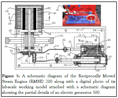
Figure 5: A schematic diagram of the Reciprocally Moved Steam Engine (RMSE) 200 along with a digital photo of its lab-scale working model attached with a schematic diagram showing the partial details of an electric generator 300.
Fabrication of reciprocally moved steam engine
The details, a digital photo revealing partial details and schematic diagram of Reciprocally Moved Steam Engine (RMSE) 200 employed in this investigation to convert the in situ generated heat energy into rotational mechanical energy. The WF 124 with a minimum pressure of >1.5 bar leaves the bottom chamber of the SLAPE solar panel 100 via a controlled valve into the steam chest 201 of RMSE 200 thereby it moves into the main cylinder 202 via inlet or outlet ports 207 and causes the movement of the piston 203 in the main cylinder so as to move it reciprocally with the help of the eccentric plate 221 connected to the main cylinder piston via a connecting rod 218 (or joint) and axle 219. When the eccentric plate 221 connected to the crank shaft 220 causes the rotation of another eccentric plate 223 sat on the crank shaft 220 adjacent to the eccentric plate 221 that is connected to the main cylinder piston.
When this latter eccentric plate 223 rotates, it also moves the sliding D valve cum piston rod (210 and 211) in the steam chest cum sliding D-valve chamber with the help of the connecting rod 213. The pitons (203 and 211) and the 218 and 213 connecting rods are joined with the help of two numbers of cross head bearings 204 and 212, respectively. When both the pistons 203 and 211 are reciprocally moved, they cause the entering and exit of the WF 124 vapor via ports 207 and 208, respectively. The one-side dead-end of the piston 203 causes the pushing off of the WF 124 vapor out of the main cylinder via exhaust port(s) 207, when it gets aligned with the opening ports of the centre hole 208 given to the piston connected to the steam chest cum sliding D-valve chamber 209. The main cylinder is connected to the steam chest cum sliding D-valve chamber 209. S5 using silver brazing technique and this latter assembly is fixed to a stand 215, which in turn is fixed to a base plate 217 using screws 214 and 216. The crank shaft 220 and flywheel 225 are fixed to the base plate 217 using two-numbers of holders 222 with the help of screws 224 (Figure 6) [17,18].
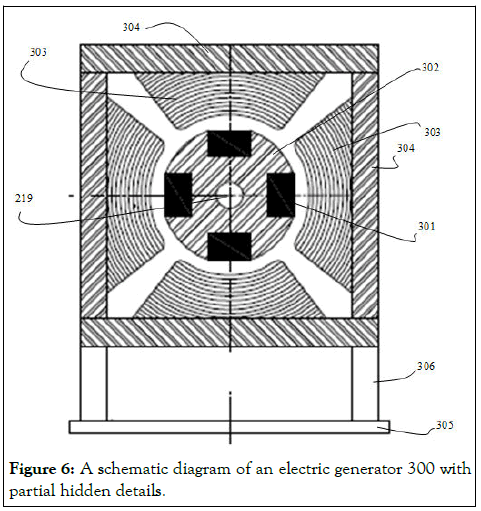
Figure 6: A schematic diagram of an electric generator 300 with partial hidden details.
Fabrication of electric generator
A custom made electric generator 300, was attached to the crankshaft 220 of the reciprocally moved steam engine 200 to generate electricity according to the principles of Faraday and Lenz laws of electromagnetic induction when the WF 124 vapor causes the movement of pistons (203 and 211) by entering via the steam chest port 201 of RMSE 200. The electric generator used in this study to generate electricity from sunlight consists of 4 numbers of rare earth neodymium (NdFeB) (Nd2Fe14B) super strong magnets (50 mm length × 10 mm width × 7 mm thick) 301, which are firmly fixed in the four slots made on a machined nylon rod 302 (40 mm diameter (ϕ) and 50 mm length).
At the centre of this nylon rod 302, a hole of 5 mm diameter is made so that it can firmly sit on the crankshaft rod 220 of the RMSE 200. The nylon rod 302 fixed with four numbers of super strong magnets 301 was placed at centre and equidistance from either four or two Cu coils 303, which are fixed to 6 mm thick transparent Polypropylene (PP) sheets 304 so that the magnets 301 placed on nylon rod 302 are easily rotated with the crankshaft 220 of the RMSE 200 at centre of these four or two Cu coils. The Cu coils are made by winding 1500 cycles of 0.2 mm diameter (ϕ) insulated wire on a PP piece of 3 mm thick × 8 mm width × 50 mm length (these PP pieces are not shown in any of the schematic diagrams for clarity purposes). These four or two numbers of 1500 turns containing Cu coils are firmly fixed to the 3 mm thick plastic sheet 305 that is fixed to the base using super strong glue (quick fix solution) with the help of 6 mm thick transparent PP legs 306 (Figure 7).
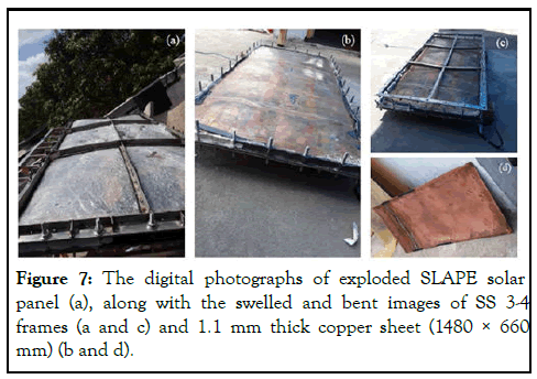
Figure 7: The digital photographs of exploded SLAPE solar panel (a), along with the swelled and bent images of SS 3-4 frames (a and c) and 1.1 mm thick copper sheet (1480 × 660 mm) (b and d).
Effects of parameters variation on the performance SLAPE solar panels
The SLAPE solar panel 100 was exposed to the sunlight by placing it on an metal stand 126 at an inclination of 30° while facing the south side between 11 am and 3 pm during the sunny days of the first-half of March month of 2020, where the average powder density of the irradiated sunlight and the average room temperature of the surrounding atmosphere were measured to be ~80 mW/cm2 and ~28°C, respectively. The dimensions of the SLAPE panels chosen for this study was based on the solar glass sheets available in the market and to have at light capturing area of least one square meter as it receives about one kWh equivalent sunlight in an hour time. This is the minimum area required to generate required pressure in DCP WF to rotate the armature of the electric generator fixed on crank shaft of RMSE to produce the measurable electricity by using a multimeter. The amount of γ-butyrolactone and the number of SPVCs present in the top-chamber of SLAPE solar panel are ~ 9 litres and 21, respectively, whereas, the bottom chamber had 2 litres of DCM WF. The heat-energy in situ generated by SPVCs and γ- butyrolactone upon exposure to sunlight has passed from topchamber to bottom chamber through the 0.5 mm thick Al metal sheet. A video showing the boiling of DCM solution upon receiving the in situ generated heat energy by SPVCs and γ- butyrolactone together and passing of thus generated heat energy from top-chamber to bottom chamber through 0.5 mm thick Al sheet that has separated these two chambers of SLAPE solar panel is given in the supporting information). The results obtained under various experimental conditions employed are given. The 0.2 mm thick copper sheet possesses four time higher thermal conductivity when compared with the 0.5 mm thick Al sheet as the thermal conductivity of the Al is half-of-the one exhibited by Cu metal. The beneficial effects of using 0.2 mm thick Cu sheet in this SLAPE solar panel can be seen from the results (Figure 8).
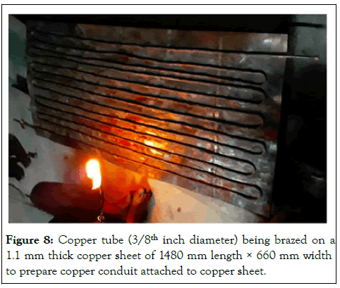
Figure 8: Copper tube (3/8th inch diameter) being brazed on a 1.1 mm thick copper sheet of 1480 mm length × 660 mm width to prepare copper conduit attached to copper sheet.
However, when the solar panel was exposed to sunlight, it started to get swelling considerably and within two hours of its exposure, it got swelled in such a way that it might explode if this exposure is continued for some more time. To avoid the explosion, the top-solar glass surface of the SLAPE solar panel was immediately covered with a black rubber sheet completely to avoid the falling of sunlight on its top surface. Furthermore, to avoid swelling of the chambers of the SLAPE solar panel, the flat shaped SS 304 frames used as tie-rods were replaced with T-shaped ones as can be seen and to avoid heat-loss through the bottom transparent soda-lime glass sheet and its breakage, it was supported with twolayers of 3 mm thick EPDM rubber sheet followed by 0.5 mm thick SS sheet and in place of 0.2 mm thick Cu sheet, a 1.1 mm thick Cu sheet was employed. When this modified SLAPE solar panel was exposed to sunlight, within 2 hours’ time, the top light transmitting solar glass got exploded completely and all the solutions from both top and bottom chambers have come out of the SLAPE solar panel as considerable amount of pressure generation was noted inside the panel as the swelling of both top and bottom chambers and the loss of heat transfer from bottom side were almost restricted. The high pressure in situ generated has severely bent the 5 mm thick SS-304 frames and 1.1 mm thick Cu sheet. This incident can be considered as a proof of the absorbance of sunlight by the SPVCS cells when fully immersed in γ-butyrolactone and generating heat-energy out of the absorbed sunlight to boil and increase the volume of DCM working fluid present in the bottom chamber. In this case, all the generated pressure can be attributed only to the evaporation of DCM WF as γ-butyrolactone (non-working fluid, NWF), does not generate any pressure below 50°C as its boiling point is 200° C (Figure 9).
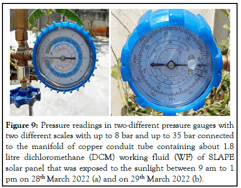
Figure 9: Pressure readings in two-different pressure gauges with two different scales with up to 8 bar and up to 35 bar connected to the manifold of copper conduit tube containing about 1.8 litre dichloromethane (DCM) working fluid (WF) of SLAPE solar panel that was exposed to the sunlight between 9 am to 1 pm on 28th March 2022 (a) and on 29th March 2022 (b).
After the SLAPE panel got exploded, a Cu tube conduit fabricated out of 3/8th diameter Cu tube was used to store the DCM WF instead of directly in the rectangular shaped bottom chamber formed between Cu and glass sheets. It was found that the rectangular shaped chambers cannot withstand high pressures without undergoing any deformation (in this case swelling) and only cylindrical shaped tubes can withstand such pressures without undergoing such dimensional changes. Probably that could be the reason behind using cylindrical shapes for all the pressure tanks and cylinders. In fact, the cylinder shape does not allow any deformation but rather it gets exploded when the inside pressure exceeds the withstanding limits of the construction material. Since, the Cu sheet employed had a thickness of 1.1 mm, the Cu conduit tube could be easily brazed to it without allowing the formation of any pin-holes and to increase the required heat transfer from top-chamber to the bottom-chamber (i.e., from γ-butyrolactone Non-Working Fluid (NWF) to the Dichloromethane (DCM) Working Fluid (WF) (Figure 10) [19].
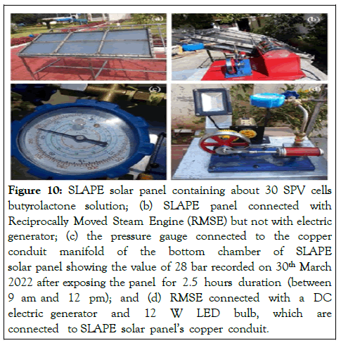
Figure 10: SLAPE solar panel containing about 30 SPV cells butyrolactone solution; (b) SLAPE panel connected with Reciprocally Moved Steam Engine (RMSE) but not with electric generator; (c) the pressure gauge connected to the copper conduit manifold of the bottom chamber of SLAPE solar panel showing the value of 28 bar recorded on 30th March 2022 after exposing the panel for 2.5 hours duration (between 9 am and 12 pm); and (d) RMSE connected with a DC electric generator and 12 W LED bulb, which are connected to SLAPE solar panel’s copper conduit.
The modified SLAPE solar panel shown in Fig. 9 (a and b) exhibited a voltage generation of about 16 V electricity with Alternating Current (AC) when exposed to sunlight for about two-hour time with the help of a RMSE and a custommade four magnets containing electric generator. The generation of 16 V electricity by this modified SLAPE solar panel can be seen in the video given in the supporting information.
The 21 SPV cells present in this SLAPE solar panel actually generates only 10 V DC electricity when they are connected in series in a commercial SPVC solar panel. However, the same 21 SPV cells in this SLAPE panel generated 16 V electricity with AC current even when the electric generator was not fabricated according to the standard design procedure. Furthermore, in another experiment conducted on 28th and 29th days of March 2022 using this modified SLAPE solar panel with 30 SPV cells, the generation of pressure exceeding the reading capabilities of the pressure gauges (>30 bar).
The glowing of a 5 W LED bulb with the pressure generated by this modified SLAPE solar panel containing 30 SPV cells with the help of a commercially available small-size DC generator can also be seen from. The amount of current generated is not measured, because these experiments were aimed only to show the Proof of Concept (PoC) of SLAPE and as there is huge heat-loss associated with the present SLAPE solar panels, which does not allow the true electricity generating capability of SLAPE solar panels.
In order to establish that the SPVCs and γ-butyrolactone are needed together to turn sunlight into heat-energy, the control experiments were also conducted. For this purpose, three SLAPE solar panels with same dimensions and using similar components were fabricated. One SLAPE solar panel had both 30 SPV cells and 2 litresγ-butyrolactone in the top-chamber, the second SLAPE panel had only 30 SPV cells in the top-chamber and the third SLAPE panel had neither SPV cells nor γ- butyrolactone in the top-chamber.
These three SLAPE solar panels had about 1.8 litres DCM solution in the bottom chambers of their copper conduits. These three SLAPE solar panels were exposed to sunlight on 5th January 2022. The pressures generated in the gauges attached to the manifolds of copper conduits are plotted. It can be seen that to generate the required pressures to rotate the reciprocally moved steam engine piston to generate electricity both SPV cells and γ-butyrolactone are compulsorily required and neither only SPV cells nor the empty top-chamber generate pressures higher than 1 bar.
On 25th February 2022 (i.e., on a normal sunny day), when a SLAPE solar panel was exposed to the sunlight and measured the temperature of its top glass surface by placing the tip of the thermometer on its top surface, a reading of about 47°C was noted in supporting information, which is about 14°C higher temperature than that of ambient room temperature of that day at about 13:30 hours (about 34°C). Surprisingly, during the measurement, a small wind-blowing was also noticed for few seconds, immediately, a reduction of about 2°C temperature in the thermometer reading was noted. It clearly indicates that there is a continuous loss of in situ generated heat into the atmosphere by means of conduction, convection and radiation through the top glass surface due to the temperature difference between SLAPE solar panel glass surface and its surroundings. This heat loss is the top-most obstacle at present preventing the achievement of higher Sunlight-to-Electricity (STE) generating conversion efficiency. The second major obstacle is the steam engine employed in these experiments is a laboratory model device designed for engineering students’ experiments purpose, which is associated with huge pressure losses from the pistoncylinder openings. At present the atmospheric weather conditions such as, ambient temperature, wind speed and its direction, humidity in the atmosphere, etc., were found to have a profound effect on the output of these SLAPE solar panels. However, their efficiency is supposed to be affected by only solar radiation but not with the atmospheric conditions. To avoid these effects, a completely adiabatically sealed SLAPE solar panel is being fabricated. Further to avoid, the sunlight reflection losses, the SPVCs will be replaced with thin black silicon wafers as these wafers do not reflect any visible light falling on them. In fact, these black silicon wafers absorb the complete sunlight reaching the earth surface with wavelength ranging from 250 nm to 2400 nm with their using surface texture. It is called black silicon because it does not reflect any light falling on it as a blackbody radiation (Figure11).
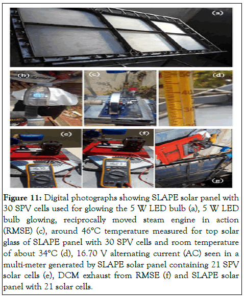
Figure 11: Digital photographs showing SLAPE solar panel with 30 SPV cells used for glowing the 5 W LED bulb (a), 5 W LED bulb glowing, reciprocally moved steam engine in action (RMSE) (c), around 46°C temperature measured for top solar glass of SLAPE panel with 30 SPV cells and room temperature of about 34°C (d), 16.70 V alternating current (AC) seen in a multi-meter generated by SLAPE solar panel containing 21 SPV solar cells (e), DCM exhaust from RMSE (f) and SLAPE solar panel with 21 solar cells.
The considerably high thermal conductivity of Borosil solar glass could be responsible for the higher amounts of in situ generated heat loss occurring through the SLAPE solar panel to the atmosphere. In fact, high thermal conducting solar glass is required for SPVC solar panels but not for SLAPE solar panels. For SPVC solar panels this highly thermal conducting Borosil solar glass is compulsory for dissipating the in situ generated heat by SPV cells as soon as possible as their efficiency is inversely proportional to the operating ambient temperature. This is the reason for the local heat island effect normally seen wherever large number of SPVC solar panels are deployed. However, the SLAPE solar panels need glass sheets with lowest possible thermal conductivity. In the control (i.e., blank) experiment, where, the SLAPE panel did not had any SPVCs γ-butyrolactone, the temperature measured on the top Borosil solar glass surface was no different from the one measured at ambient room temperature although certain pressure was noted the Cu conduit containing DCM WF. These results clearly suggest that the semiconducting materials along with a suitable solvent are compulsory to capture the sunlight and to turn it into the heatenergy. When wind was blowing, the increased heat-loss was also noted. In fact, the entire SLAPE technology is based on the heatenergy in situ generated from sunlight before converting it into electricity. Now in these present SLAPE solar panels, most of the in situ generated heat energy is continuously losing into the atmosphere. Unless such leakages are completely arrested, it is not possible to achieve the desired conversion of STE efficiency for these SLAPE solar panels [20].
The Semiconductor and Liquid Assisted Photothermal Effect (SLAPE) solar panels were designed and fabricated to generate electricity from sunlight by following a new concept that was not reported so far. In this study, the few numbers of SLAPE solar panels fabricated and investigated to establish the proof of concept of this SLAPE mechanism. In the fabrication of SLAPE solar panels with about a one square meter area, 21 numbers of multicrystalline Silicon Photovoltaic Cells (SPVCs) together with about 2 litres γ-butyrolactone were employed. This latter SLAPE solar panel exhibited about 17 V electricity when attached with a laboratory model Reciprocally Moved Steam Engine (RMSE) and a custom-made electric generator. In commercial SPVC solar panels, the 21 number SPV cells generate a maximum voltage of only about 11 V electricity but in this case, these SLAPE solar panels exhibited about 17 V. There a great amount of scope for the improvement of efficiency of these SLAPE solar panels by employing right kinds of components and systems. Further studies are under progress to improve the electricity generating efficiency of the SLAPE solar panels by utilizing improved components and systems such as, better heat-engines, black silicon wafers and flat-plate double lined vacuum chambers as top-solar glass components. This latter flat-plate vacuum chambers shall work like a wall in the Dewar (i.e., Thermos) flask in terms of arresting the heat-transfer from the SLAPE solar panel into the atmosphere.
Author wishes to thank the Department of Science and Technology (DST), New Delhi, Government of India, for Science and Engineering Research Board (SERB)-Empowerment and Equity Opportunities for Excellence in Science (EMEQ) scheme (#SB/EMEQ-218/2014).
[Crossref] [Google Scholar] [PubMed]
[Crossref] [Google Scholar] [PubMed]
[Crossref] [Google Scholar] [PubMed]
[Crossref] [Google Scholar] [PubMed]
[Crossref] [Google Scholar] [PubMed]
[Crossref] [Google Scholar] [PubMed]
[Crossref] [Google Scholar] [PubMed]
[Crossref] [Google Scholar] [PubMed]
Citation: Ibram Ganesh (2024) Semiconductor and Liquid Assisted Photothermal Effect: A New Method to Generate Electricity from Sunlight. J Phys Chem Biophys. 14:399.
Received: 22-Nov-2023, Manuscript No. JPCB-24-28111; Editor assigned: 27-Nov-2023, Pre QC No. JPCB-24-28111 (PQ); Reviewed: 11-Dec-2023, QC No. JPCB-24-28111; Revised: 01-Oct-2024, Manuscript No. JPCB-24-28111 (R); Published: 29-Oct-2024 , DOI: 10.35841/2161-0398.24.14.399
Copyright: © 2024 Ganesh I. This is an open-access article distributed under the terms of the Creative Commons Attribution License, which permits unrestricted use, distribution and reproduction in any medium, provided the original author and source are credited.