Journal of Aeronautics & Aerospace Engineering
Open Access
ISSN: 2168-9792
ISSN: 2168-9792
Research Article - (2017) Volume 6, Issue 1
Composite lattice structures are shells that are reinforced by unidirectional helical and hoop ribs. Their main advantage over contemporary composite structures is their superior stiffness to mass ratio. However, their application in industry is still limited. In this paper, the lattice structure concept was applied for the case of a small business aircraft. Emphasis here is given at the initial stages of the design. More specifically, the buckling modes for bending loads were calculated by utilizing a continum unit cell model which was correlated with finite element models for a cylindrical small fuselage structure and two scaled down versions.
<Composite lattice strictures are composed of helical and hoop ribs that reinforce a shell. They are characterized by high specific strength and stiffness, making them promising for lightweight applications. The history and development of this kind of structures can be found in literature, mostly published by Vasiliev et al. [1-5].
Lattice structures are using reinforcing ribs in a regular pattern, which allows to be analyzed by smearing the ribs over the skin surface. Thus, the lattice structure can be analyzed as a continuous layer with calculated effective stiffness. Stress and strain equations that are based on theory of orthotropic shells can be used. Such continuum models are published by Vasiliev [6] and Vasiliev and Morozov [7]. Strength and buckling analysis of cylindrical lattice shells based on different continuum models are described in articles from Slinchenko and Verijenko [8], Totaro and Gurdal [9], Buragohain and Velmurugan [10], Paschero and Hyer [11], Totaro [12,13], and Zheng et al. [14].
Additionally, composite lattice structures have been analyzed by using finite element analysis. Results from FE models can be found in articles published by Hou et al., Zhang et al., Frulloni et al., Fan et al., Morozov et al. and Azarov et al. [15-20].
However, in most applications, both methodologies are used, where the basic specifications of the structure are calculated by employing the continuum models. The parameters are then further refined by using the finite element models. Correlation between these methodologies has been done successfully by Azarov [20].
Despite the aforementioned developments in designing composite lattice structures, their application is still limited in some spacecraft applications [3,21].
In this work, the case of a fuselage section of a small business aircraft is examined. The fuselage section has an outer diameter of 1.8 m and a length of 4 m. The fuselage section was assumed to be subjected to buckling loads and its buckling limit was calculated by a smeared unit cell method and finite element analysis. Furthermore, a scaling down approach was followed for estimating the buckling loads for scaled down prototypes, namely 0.5 and 1 m in diameter. The scaling down approach is useful since many times full scale testing is prohibited for this kind of structures since they are integrated with no assembly required, making testing of single subcomponents not feasible. The correlation between the smeared unit cell theory and finite element analysis was very good.
In developing the analytical model, a unit cell of the stiffener structure has to be defined first. The unit cell is chosen such that the whole grid structure can be reproduced by repetition of this unit cell.
The equivalent stiffness parameters of this unit are determined and then applied to the whole cylinder panel. Validation comes from the generation of the panel by repetition of the cell.
1. The transverse modulus of the unidirectional stiffeners is much lower than the longitudinal modulus, and cross sectional dimensions are also very small compared to the length dimension, therefore the stiffeners are assumed to support axial loads only.
2. The strain is uniform across the cross sectional area of the stiffeners. Hence a uniform stress distribution is assumed.
3. Load is transferred through shear forces between the stiffeners and the shell.
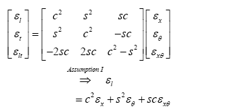
Strains used as the matching condition of the stiffener and the shell (inner surface of the shell as interface) is given by:
 (1)
(1)
 (2)
(2)
 (3)
(3)
Strain relationship along the stiffeners’ directions is given by:
 (4)
(4)
Where c=cos(ϕ), s=sin(ϕ) and ϕ is the stiffener orientation angle from vertical direction.
In this specific case of study, ϕ±26° was selected for the helical ribs and ϕ=90° was selected for the hoop ribs (Figure 1).
Resultant Forces of the force diagram is as shown below (Figure 2):
 (5)
(5)
 (6)
(6)
 (7)
(7)
Summing up the forces of each opposite sides in both directions, Fx and Fθ are obtained:
 (8)
(8)
 (9)
(9)
 (10)
(10)
Resultant Forces on the unit cell is given by:
 (11)
(11)
 (12)
(12)
 (13)
(13)
Following the same procedure as the force analysis on the unit cell, resultant moments are computed with respect to the moment diagram (Figure 3):
 (14)
(14)
 (15)
(15)
 (16)
(16)
Resultant Moments on the unit cell:
 (17)
(17)
 (18)
(18)
 (19)
(19)
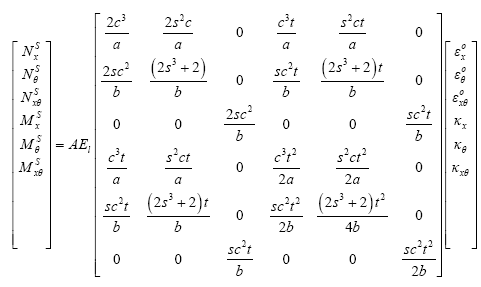
The functions of the mid plane strains of the shell then become:
 (20)
(20)
The superscript‘s’ denotes the force and moment contributions of the stiffener.
By applying the Rule of Mixtures, the forces and the moments are superimposed according to the volume fractions of the stiffeners (VS) and the shell (VSh).
 (21)
(21)
The resultant stiffness parameters obtained from the above equation are the equivalent stiffness parameters of the whole panel.
For the calculation of the critical buckling load, the Ritz method (Przemieniecki, 1968) was used which is based on the minimization of the total energy Π of the cylinder. The total energy of the cylindrical structure is the sum of the strain energy U and the external force work V.
 (22)
(22)
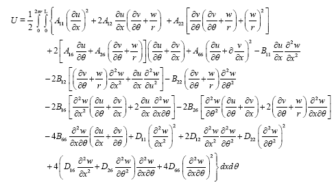
The strain energy of an orthotropic cylinder with length L is given by the following equation:
 (23)
(23)
U is dependent from the total stiffness matrix of the unit cell, radius r of the cylinder and axial, circumferential and radial displacements u, v, w respectively.
The dynamic energy term V, due to the external work for length L is given by:
 (24)
(24)
The displacement field u, v and w are defined by kinematically admissible functions and they are approximated by a double Fourier series with clamped boundary condition:
 (25)
(25)
 (26)
(26)
 (27)
(27)

m, n = 1,2,3…
The total energy expression is a function of the stiffness matrix elements of the equivalent laminate and the unknown displacement field coefficients Amn, Bmn and Dmn. For the equilibrium to be stable, the total potential energy of the system must be minimum. This can be satisfied by finding the first derivative of the total potential energy with respect to the unknown constants Amn, Bmn and Dmn and equating to zero. This results in an eigenvalue problem. The resulting Equation is then solved for the unknown in-plane load Nx.
The specifications for the lattice with 1.8 m diameter are summarized in Table 1, whereas the material properties in Table 2 (Tables 1 and 2).
| Parameter | [90/±26º] ribs orientation |
|---|---|
| Material | HTS5631 |
| Skin Thickness, mm | 1.4 |
| No of Reels (each side) | 20 |
| No. of Helical ribs | 40 |
| No of Circum. Hoops | 6 |
| Area of Rib Section, mm2 | 134 |
| Mass, Kg | 48.8 |
Table 1: Specifications for lattice fuselage structures.
| Property | Value |
|---|---|
| Young's modulus E1 | 128.9GPa |
| Young's modulus E2 | 10.4 GPa |
| Shear modulus G12 | 4.11 GPa |
| v12 | 0.34 |
| Thickness t | 0.35 mm |
Table 2: HTS-5631 material properties.
By using the above requirements and theory, a MATLAB code was written where the buckling load was calculated and verified by finite element analysis using MSC NASTRAN. The Finite element model consisted of 4400 beam elements for the hoop and helical ribs and 12000 shell elements for the composite skin. The one side of the model was clamped whereas the other one was subjected to a compressive load which was distributed to the nodes via multi-point constraints (MPCs). The first buckling mode from the finite element model of the full scale fuselage is shown in Figure 3, whereas the comparison with the unit cell analysis is shown in Table 3 (Figures 2 and 3).
| Calculation method | Full Scale prototype 1.8m in diameter, 2m in length |
|---|---|
| Buckling load calculated by FEM | 467.9 kN |
| Buckling load calculated analytically | 463.9 kN |
Table 3: Computation of full scale fuselage buckling load by unit cell method and finite element analysis.
In order to scale down the wafer to the desired main dimensions, the analysis was based on the of buckling load/mass ratio (Pcr/M) of the scaled down structure versus the cross-sectional area (Asc) of the ribs. Moreover, the number of reels was decreased with respect to manufacturing restrictions, such as keeping the spacing between the reels the same. Finally, the skin thickness remained constant, since further scaling down its thickness below the four layers with total thickness of 1.4 mm was not possible because it could lead to an unsymmetrical fuselage skin layup. Given the above descriptions, a parametric analysis was done with the unit cell theory, in order to extract the required ribs cross section for two scaled down fuselage geometries with 1 m and 0.5 m in diameter. The results for both scaled down structures are summarized in Figures 4 and 5, where the ratio of critical buckling load to mass (Pcr/M) against ribs cross section is shown. The results were used with final goal to achieve the same Pcr/M ratio with the full scale fuselage (Figures 4 and 5).
The final step was the correlation of the unit cell models of the scaled down structures with finite element models. Figure 6 depicts the first buckling mode for the 1 m diameter prototype whereas Figure 7 shows the first buckling mode of the 0.5 m diameter scaled down structure. Table 4 shows the comparison of the critical buckling loads by finite element models and unit cell method (Figures 6 and 7).
| Scaled down prototype 1m in diameter, 1m in length | Scaled down prototype 0.5m in diameter, 1m in length | |
|---|---|---|
| Buckling load calculated by FEM | 263.9 kN | 136.5 kN |
| Buckling load calculated analytically | 260.6 kN | 132.1 kN |
Table 4: The comparison of the critical buckling loads by finite element models and unit cell method.
A smeared unit cell analytical solution has been developed for the case of a small business aircraft fuselage section, which was also correlated with finite element analysis approach. Afterwards, a scaling down approach was followed for two scaled down fuselage structures. By keeping the skin thickness the same and reducing the full scale fuselage diameter, the ribs cross section and distance were calculated in order to achieve the same buckling load to mass ratio. All models have shown an excellent correlation between the unit cell approach and the finite element analysis.
Moreover, a close to linear relationship was found between the buckling load and the diameter of the structures, enabling testing and validation of computational tools in scaled down prototypes.